NLX2G07BMX1TCG ON Semiconductor, NLX2G07BMX1TCG Datasheet
NLX2G07BMX1TCG
Specifications of NLX2G07BMX1TCG


Related parts for NLX2G07BMX1TCG

NLX2G07BMX1TCG Summary of contents
Page 1
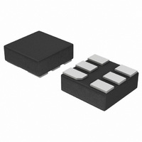
NLX2G07 Dual Non-Inverting Buffer, Open Drain The NLX2G07 MiniGatet is an advanced high-speed CMOS dual non-inverting buffer with open drain output in ultra-small footprint. The NLX2G07 input and output structures provide protection when voltages up to 7.0 V are applied, ...
Page 2
MAXIMUM RATINGS Symbol V DC Supply Voltage Input Voltage Output Voltage OUT I DC Input Diode Current Output Diode Current Output Source/Sink Current Supply Current ...
Page 3
DC ELECTRICAL CHARACTERISTICS Symbol Parameter Conditions V Low-Level IH Input Voltage V Low-Level IL Input Voltage V Low-Level Output I OL Voltage ...
Page 4
AC ELECTRICAL CHARACTERISTICS Symbol Parameter t Propagation Delay PZL (Figures 3 and 4) t Propagation Delay PLZ (Figures 3 and 4) C Input Capacitance IN C Output Capacitance OUT C Power Dissipation Capacitance PD (Note defined ...
Page 5
... ORDERING INFORMATION Device NLX2G07AMX1TCG NLX2G07BMX1TCG NLX2G07CMX1TCG †For information on tape and reel specifications, including part orientation and tape sizes, please refer to our Tape and Reel Packaging Specifications Brochure, BRD8011/D. NLX2G07 Package ULLGA6, 1.45 x 1.0, 0.5P (Pb-Free) ULLGA6, 1.2 x 1.0, 0.4P (Pb-Free) ULLGA6, 1.0 x 1.0, 0.35P (Pb-Free) http://onsemi ...
Page 6
... OUTLINE *For additional information on our Pb-Free strategy and soldering C NOTE 3 details, please download the ON Semiconductor Soldering and Mounting Techniques Reference Manual, SOLDERRM/D. http://onsemi.com 6 ASME Y14.5M, 1994. AND IS MEASURED BETWEEN 0.15 AND 0.30 mm FROM THE TERMINAL TIP. PLATED TERMINAL FROM THE EDGE OF THE PACKAGE IS ALLOWED ...
Page 7
... *For additional information on our Pb-Free strategy and soldering 0.05 C NOTE 3 details, please download the ON Semiconductor Soldering and Mounting Techniques Reference Manual, SOLDERRM/D. http://onsemi.com 7 1. DIMENSIONING AND TOLERANCING PER ASME Y14.5M, 1994. 2. CONTROLLING DIMENSION: MILLIMETERS. 3. DIMENSION b APPLIES TO PLATED TERMINAL AND IS MEASURED BETWEEN 0.15 AND ...
Page 8
... A B *For additional information on our Pb-Free strategy and soldering 0.05 C NOTE 3 details, please download the ON Semiconductor Soldering and Mounting Techniques Reference Manual, SOLDERRM/D. N. American Technical Support: 800-282-9855 Toll Free USA/Canada Europe, Middle East and Africa Technical Support: Phone: 421 33 790 2910 Japan Customer Focus Center ...