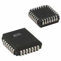
SY10E151JC Micrel Inc, SY10E151JC Datasheet - Page 3

SY10E151JC
Manufacturer Part Number
SY10E151JC
Description
IC REGISTER D 6-BIT 28-PLCC
Manufacturer
Micrel Inc
Series
10Er
Type
D-Type Busr
Datasheet
1.SY100E151JZ.pdf
(4 pages)
Specifications of SY10E151JC
Function
Master Reset
Output Type
Differential
Number Of Elements
1
Number Of Bits Per Element
6
Frequency - Clock
1.4GHz
Trigger Type
Positive Edge
Voltage - Supply
4.2 V ~ 5.5 V
Operating Temperature
0°C ~ 85°C
Mounting Type
Surface Mount
Package / Case
28-LCC (J-Lead)
Lead Free Status / RoHS Status
Contains lead / RoHS non-compliant
Current - Output High, Low
-
Delay Time - Propagation
-
Available stocks
Company
Part Number
Manufacturer
Quantity
Price
Company:
Part Number:
SY10E151JC
Manufacturer:
SYNERGY
Quantity:
11 040
Part Number:
SY10E151JC
Manufacturer:
SYNERGY
Quantity:
20 000
Micrel, Inc.
Asynchronous Operation
Note:
1. H = HIGH Voltage Level
V
Note:
1. Specification for packaged product only.
V
Note:
1. Within-device skew is defined as identical transitions on similar paths through a device.
2. Specification for packaged product only.
M9999-052108
hbwhelp@micrel.com or (408) 955-1690
Symbol
I
I
Symbol
f
t
t
t
t
t
t
t
t
EE
EE
IH
EE
MAX
PD
S
H
RR
PW
skew
r
f
TRUTH TABLES
DC ELECTRICAL CHARACTERISTICS
AC ELECTRICAL CHARACTERISTICS
L = LOW Voltage Level
X = Don’t Care
t = Time before positive CLK transition
t+1 = Time after positive CLK transition
u = LOW-to-HIGH transition
D
= V
= V
X
n
EE
EE
Max. Toggle Frequency
Propagation Delay to Output
CLK
MR
Set-up Time, D
Hold Time, D
Reset Recovery Time
Minimum Pulse Width
CLK, MR
Within-Device Skew
Rise/Fall Time
20% to 80%
(Min.) to V
(Min.) to V
Input HIGH Current
Power Supply Current
CLK
X
Parameter
Parameter
1
Inputs
EE
EE
(1)
(Max.); V
(Max.); V
CLK
X
2
100E
10E
CC
CC
MR
= V
= V
H
1100 1400
Min. Typ. Max. Min. Typ.
Min. Typ. Max. Min. Typ.
475
475
350
750
400
300
—
—
—
—
CCO
0
CCO
T
T
A
A
–175
= GND
= GND
650
650
175
550
450
65
65
65
= 0 C
—
= 0 C
—
Q
Output
n
(t + 1)
L
(1)
(2)
150
800
850
700
78
78
—
—
—
—
—
—
1100 1400
475
475
350
750
400
300
—
—
—
—
0
T
T
3
A
A
Synchronous Operation
= +25 C
= +25 C
–175
650
650
175
550
450
65
65
65
—
—
D
H
H
X
X
X
L
L
n
Max. Min. Typ.
Max. Min. Typ.
150
800
850
700
78
78
—
—
—
—
—
—
1100 1400
CLK
475
475
350
750
400
300
—
—
—
—
0
H
u
u
L
L
u
L
T
T
A
A
1
Inputs
= +85 C
= +85 C
–175
650
650
175
550
450
65
75
65
—
—
CLK
Max.
Max.
H
L
L
u
u
u
L
150
800
850
700
78
90
—
—
—
—
—
—
2
MHz
Unit
Unit
mA
ps
ps
ps
ps
ps
ps
ps
A
MR
L
L
L
L
L
L
L
Condition
Condition
Q
Output
n
—
—
—
—
—
—
—
—
—
Q
Q
Q
SY100E151
1
(t + 1)
SY10E151
H
H
n
n
n
L
L
(t)
(t)
(t)


