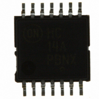
MC74HC14ADTG ON Semiconductor, MC74HC14ADTG Datasheet - Page 8

MC74HC14ADTG
Manufacturer Part Number
MC74HC14ADTG
Description
IC SCHMITT TRIG INV HEX 14-TSSOP
Manufacturer
ON Semiconductor
Series
74HCr
Datasheet
1.MC74HC14ANG.pdf
(10 pages)
Specifications of MC74HC14ADTG
Logic Type
Inverter with Schmitt Trigger
Number Of Inputs
1
Number Of Circuits
6
Current - Output High, Low
5.2mA, 5.2mA
Voltage - Supply
2 V ~ 6 V
Operating Temperature
-55°C ~ 125°C
Mounting Type
Surface Mount
Package / Case
14-TSSOP
Logic Family
74HC
High Level Output Current
- 5.2 mA
Low Level Output Current
5.2 mA
Propagation Delay Time
75 ns, 30 ns, 15 ns, 13 ns
Supply Voltage (max)
6 V
Supply Voltage (min)
2 V
Maximum Operating Temperature
+ 125 C
Mounting Style
SMD/SMT
Operating Supply Voltage
2 V to 6 V
Logical Function
Inverter Schmit Trig
Number Of Elements
6
Input Type
Schmitt Trigger
Operating Supply Voltage (typ)
2.5/3.3/5V
Package Type
TSSOP
Operating Temp Range
-55C to 125C
Pin Count
14
Quiescent Current
1uA
Output Type
Schmitt Trigger
Technology
CMOS
Mounting
Surface Mount
Operating Temperature Classification
Military
Operating Supply Voltage (max)
6V
Operating Supply Voltage (min)
2V
Output Current
5.2mA
No. Of Inputs
1
Supply Voltage Range
2V To 6V
Logic Case Style
TSSOP
No. Of Pins
14
Lead Free Status / RoHS Status
Lead free / RoHS Compliant
Other names
MC74HC14ADTG
MC74HC14ADTGOS
MC74HC14ADTGOS
SEATING
PLANE
−T−
14
1
G
−A−
D
14 PL
0.25 (0.010)
M
*For additional information on our Pb−Free strategy and soldering
8
7
details, please download the ON Semiconductor Soldering and
Mounting Techniques Reference Manual, SOLDERRM/D.
−B−
0.58
T
14X
K
B
S
C
P
7 PL
A
SOLDERING FOOTPRINT*
S
0.25 (0.010)
PACKAGE DIMENSIONS
R
http://onsemi.com
1
X 45
CASE 751A−03
_
M
SOIC−14
ISSUE H
M
7.04
7X
B
8
M
DIMENSIONS: MILLIMETERS
J
1.52
14X
F
1.27
PITCH
NOTES:
1. DIMENSIONING AND TOLERANCING PER
2. CONTROLLING DIMENSION: MILLIMETER.
3. DIMENSIONS A AND B DO NOT INCLUDE
4. MAXIMUM MOLD PROTRUSION 0.15 (0.006)
5. DIMENSION D DOES NOT INCLUDE
ANSI Y14.5M, 1982.
MOLD PROTRUSION.
PER SIDE.
DAMBAR PROTRUSION. ALLOWABLE
DAMBAR PROTRUSION SHALL BE 0.127
(0.005) TOTAL IN EXCESS OF THE D
DIMENSION AT MAXIMUM MATERIAL
CONDITION.
DIM
G
M
A
B
C
D
F
J
K
P
R
MILLIMETERS
MIN
8.55
3.80
1.35
0.35
0.40
0.19
0.10
5.80
0.25
1.27 BSC
0
_
MAX
8.75
4.00
1.75
0.49
1.25
0.25
0.25
6.20
0.50
7
_
0.337
0.150
0.054
0.014
0.016
0.008
0.004
0.228
0.010
MIN
0.050 BSC
0
INCHES
_
0.344
0.157
0.068
0.019
0.049
0.009
0.009
0.244
0.019
MAX
7
_


