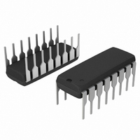
MC14504BCPG ON Semiconductor, MC14504BCPG Datasheet - Page 7

MC14504BCPG
Manufacturer Part Number
MC14504BCPG
Description
IC TRANSLATOR HEX CMOS 16DIP
Manufacturer
ON Semiconductor
Series
4000Br
Specifications of MC14504BCPG
Logic Function
Level Shifter
Number Of Bits
6
Input Type
TTL, CMOS
Output Type
CMOS
Number Of Channels
6
Number Of Outputs/channel
1
Differential - Input:output
No/No
Propagation Delay (max)
280ns
Voltage - Supply
3 V ~ 18 V
Operating Temperature
-55°C ~ 125°C
Package / Case
16-DIP (0.300", 7.62mm)
Supply Voltage
3 V ~ 18 V
Logic Type
Voltage Level Shifter
Logic Family
4000
Translation
CMOS/TTL to CMOS
Input Bias Current (max)
5 mA
High Level Output Current
- 4.2 mA (Min)
Low Level Output Current
4.2 mA (Min)
Propagation Delay Time
550 ns @ 5 V @ 15 V
Supply Voltage (max)
18 V
Supply Voltage (min)
3 V
Maximum Operating Temperature
+ 125 C
Minimum Operating Temperature
- 55 C
Mounting Style
Through Hole
Circuit Type
Low-Power Schottky
Current, Supply
6 mA
Function Type
1-Channel
Number Of Circuits
Hex
Package Type
PDIP-16
Special Features
Non-Inverting
Temperature, Operating, Range
-55 to +125 °C
Voltage, Supply
3 to 18 VDC
Lead Free Status / RoHS Status
Lead free / RoHS Compliant
Data Rate
-
Lead Free Status / Rohs Status
Lead free / RoHS Compliant
Other names
MC14504BCPGOS
Available stocks
Company
Part Number
Manufacturer
Quantity
Price
Company:
Part Number:
MC14504BCPG
Manufacturer:
SILERGY
Quantity:
72 000
Part Number:
MC14504BCPG
Manufacturer:
ON/安森美
Quantity:
20 000
e
16
1
0.13 (0.005)
Z
b
D
M
9
8
A
E
0.10 (0.004)
A
H
1
E
VIEW P
PLASTIC EIAJ SOIC PACKAGE
PACKAGE DIMENSIONS
M
_
http://onsemi.com
L
E
CASE 966−01
MC14504B
SOEIAJ−16
F SUFFIX
ISSUE O
L
DETAIL P
7
Q
1
c
NOTES:
1.
2.
3.
4.
5.
Y14.5M, 1982.
MOLD FLASH OR PROTRUSIONS AND ARE
MEASURED AT THE PARTING LINE. MOLD FLASH
OR PROTRUSIONS SHALL NOT EXCEED 0.15
(0.006) PER SIDE.
REFERENCE ONLY.
INCLUDE DAMBAR PROTRUSION. ALLOWABLE
DAMBAR PROTRUSION SHALL BE 0.08 (0.003)
TOTAL IN EXCESS OF THE LEAD WIDTH
DIMENSION AT MAXIMUM MATERIAL CONDITION.
DAMBAR CANNOT BE LOCATED ON THE LOWER
RADIUS OR THE FOOT. MINIMUM SPACE
BETWEEN PROTRUSIONS AND ADJACENT LEAD
TO BE 0.46 ( 0.018).
H
DIM
A
L
M
A
b
c
D
E
e
L
Q
Z
E
E
1
DIMENSIONING AND TOLERANCING PER ANSI
CONTROLLING DIMENSION: MILLIMETER.
DIMENSIONS D AND E DO NOT INCLUDE
TERMINAL NUMBERS ARE SHOWN FOR
THE LEAD WIDTH DIMENSION (b) DOES NOT
1
MILLIMETERS
MIN
0.05
0.35
0.18
9.90
5.10
7.40
0.50
0.70
1.10
−−−
−−−
0
1.27 BSC
_
10.50
MAX
10
2.05
0.20
0.50
0.27
5.45
8.20
0.85
1.50
0.90
0.78
_
0.002
0.014
0.007
0.390
0.201
0.291
0.020
0.043
0.028
MIN
−−−
−−−
0.050 BSC
0
INCHES
_
0.081
0.008
0.020
0.413
0.215
0.323
0.033
0.059
0.035
0.031
MAX
0.011
10
_


