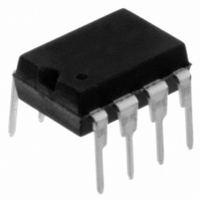
11LC160-I/P Microchip Technology, 11LC160-I/P Datasheet - Page 4

11LC160-I/P
Manufacturer Part Number
11LC160-I/P
Description
IC EEPROM 16KBIT 100KHZ 8DIP
Manufacturer
Microchip Technology
Datasheets
1.11LC010T-ITT.pdf
(44 pages)
2.11LC010T-ITT.pdf
(22 pages)
3.11LC010T-ITT.pdf
(6 pages)
4.11LC160T-ITT.pdf
(38 pages)
Specifications of 11LC160-I/P
Memory Size
16K (2K x 8)
Package / Case
8-DIP (0.300", 7.62mm)
Operating Temperature
-40°C ~ 85°C
Format - Memory
EEPROMs - Serial
Memory Type
EEPROM
Speed
100kHz
Interface
UNI/O™ (Single Wire)
Voltage - Supply
2.5 V ~ 5.5 V
Organization
2048 x 8
Interface Type
Serial
Maximum Clock Frequency
100 KHz
Supply Voltage (max)
5.5 V
Supply Voltage (min)
2.5 V
Maximum Operating Current
50 uA
Maximum Operating Temperature
+ 85 C
Mounting Style
Through Hole
Minimum Operating Temperature
- 40 C
Operating Supply Voltage
3.3 V, 5 V
Lead Free Status / RoHS Status
Lead free / RoHS Compliant
Lead Free Status / RoHS Status
Lead free / RoHS Compliant, Lead free / RoHS Compliant
11AAXXX/11LCXXX
TABLE 1-2:
TABLE 1-3:
DS22067H-page 4
AC CHARACTERISTICS
Note 1: This parameter is periodically sampled and not 100% tested.
AC Waveform:
Timing Measurement Reference Level
Param.
No.
10
11
12
13
14
1
2
3
4
5
6
7
8
9
V
V
C
Input
Output
LO
HI
L
2: This parameter is not tested but ensured by characterization. For endurance estimates in a specific
3:
= 100 pF
= V
= 0.2V
F
T
Sym.
application, please consult the Total Endurance
www.microchip.com.
F
F
T
T
T
T
DRIFT
STBY
T
T
A Unit Interval (UI) is equal to 1-bit period (T
OJIT
T
BUS
T
DEV
T
HDR
—
IJIT
WC
SS
SP
CC
E
R
F
- 0.2V
AC CHARACTERISTICS
AC TEST CONDITIONS
Serial bus frequency
Bit period
Input edge jitter tolerance
Serial bus frequency drift
rate tolerance
Serial bus frequency drift
limit
Output edge jitter
SCIO input rise time
(Note 1)
SCIO input fall time
(Note 1)
Standby pulse time
Start header setup time
Start header low pulse
time
Input filter spike
suppression (SCIO)
Write cycle time
(byte or page)
Endurance (per page)
Characteristic
0.5 V
0.5 V
Electrical Characteristics:
Industrial (I):
Automotive (E):
CC
CC
Min.
600
1M
10
10
10
—
—
—
—
—
—
—
—
—
Preliminary
5
E
) at the current bus frequency.
™
±0.08
±0.75
±0.25
Model which can be obtained on Microchip’s web site:
Max.
100
100
100
100
±5
50
10
—
—
—
—
5
V
V
V
CC
CC
CC
% per byte —
command
= 1.8V to 2.5V
= 2.5V to 5.5V
= 2.5V to 5.5V
cycles
% per
Units
kHz
ms
ms
µs
µs
µs
µs
UI
UI
ns
ns
ns
—
—
25°C, V
—
(Note 3)
—
(Note 3)
—
—
—
—
(Note 1)
Write, WRSR commands
ERAL, SETAL commands
2010 Microchip Technology Inc.
CC
T
T
T
Test Conditions
A
A
A
= 5.5V (Note 2)
= -40°C to +85°C
= -20°C to +85°C
= -40°C to +125°C


