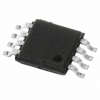
M93C46-WDW6TP STMicroelectronics, M93C46-WDW6TP Datasheet - Page 9

M93C46-WDW6TP
Manufacturer Part Number
M93C46-WDW6TP
Description
IC EEPROM 1KBIT 2MHZ 8TSSOP
Manufacturer
STMicroelectronics
Specifications of M93C46-WDW6TP
Format - Memory
EEPROMs - Serial
Memory Type
EEPROM
Memory Size
1K (128 x 8 or 64 x 16)
Speed
2MHz
Interface
Microwire, 3-Wire Serial
Voltage - Supply
2.5 V ~ 5.5 V
Operating Temperature
-40°C ~ 85°C
Package / Case
8-TSSOP
Organization
128 K x 8
Interface Type
Microwire
Maximum Clock Frequency
2 MHz
Supply Voltage (max)
5.5 V
Supply Voltage (min)
2.5 V
Maximum Operating Current
2 mA
Maximum Operating Temperature
+ 85 C
Mounting Style
SMD/SMT
Minimum Operating Temperature
- 40 C
Operating Supply Voltage
2.5 V, 5.5 V
Lead Free Status / RoHS Status
Lead free / RoHS Compliant
Other names
497-8655-2
M93C46-WDW6TP
M93C46-WDW6TP
Available stocks
Company
Part Number
Manufacturer
Quantity
Price
Company:
Part Number:
M93C46-WDW6TP
Manufacturer:
STMicroelectronics
Quantity:
28 615
Company:
Part Number:
M93C46-WDW6TP
Manufacturer:
SANYO
Quantity:
2 449
Part Number:
M93C46-WDW6TP
Manufacturer:
ST
Quantity:
20 000
M93C86, M93C76, M93C66, M93C56, M93C46
2
Connecting to the serial bus
Figure 3
Only one device is selected at a time, so only one device drives the Serial Data output (Q)
line at a time, the other devices are high impedance.
The pull-down resistor R (represented in
bus master leaves the S line in the high impedance state.
In applications where the bus master may be in a state where all inputs/outputs are high
impedance at the same time (for example, if the bus master is reset during the transmission
of an instruction), the clock line (C) must be connected to an external pull-down resistor so
that, if all inputs/outputs become high impedance, the C line is pulled low (while the S line is
pulled low): this ensures that C does not become high at the same time as S goes low, and
so, that the t
Figure 3.
CS3 CS2 CS1
Bus master
shows an example of three memory devices connected to an MCU, on a serial bus.
SLCH
Bus master and memory devices on the serial bus
SDO
SCK
SDI
requirement is met. The typical value of R is 100 k .
R
R
C Q D
S
memory device
Doc ID 4997 Rev 11
M93xxx
ORG
V
CC
Figure
V
R
SS
3) ensures that no device is selected if the
C Q D
memory device
S
M93xxx
ORG
V
CC
Connecting to the serial bus
V
R
SS
C Q D
memory device
S
M93xxx
V
CC
ORG
AI14377b
V
SS
V
V
CC
SS
9/36


