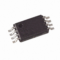
AT34C02B-10TU-1.7 Atmel, AT34C02B-10TU-1.7 Datasheet - Page 10

AT34C02B-10TU-1.7
Manufacturer Part Number
AT34C02B-10TU-1.7
Description
IC EEPROM 2KBIT 400KHZ 8TSSOP
Manufacturer
Atmel
Datasheet
1.AT34C02B-10TU-1.7.pdf
(21 pages)
Specifications of AT34C02B-10TU-1.7
Format - Memory
EEPROMs - Serial
Memory Type
EEPROM
Memory Size
2K (256 x 8)
Speed
100kHz, 400kHz
Interface
I²C, 2-Wire Serial
Voltage - Supply
1.7 V ~ 3.6 V
Operating Temperature
-40°C ~ 85°C
Package / Case
8-TSSOP
Lead Free Status / RoHS Status
Lead free / RoHS Compliant
Available stocks
Company
Part Number
Manufacturer
Quantity
Price
Company:
Part Number:
AT34C02B-10TU-1.7
Manufacturer:
ATMEL
Quantity:
80 000
Part Number:
AT34C02B-10TU-1.7
Manufacturer:
ATMEL/爱特梅尔
Quantity:
20 000
Write Protection
10
AT34C02B
The software write protection, once enabled, write protects only the first-half of the array
(00H - 7FH) while the hardware write protection, via the WP pin, is used to protect the
entire array.
PERMANENT SOFTWARE WRITE PROTECTION: The software write protection is
enabled by sending a command, similar to a normal write command, to the device which
programs the permanent write protect register. This must be done with the WP pin low.
The write protect register is programmed by sending a write command with the device
address of 0110 instead of 1010 with the address and data bit being don’t cares (see
Figure 7 on page 10). Once the software write protection has been enabled, the device
will no longer acknowledge the 0110 control byte. The software write protection cannot
be reversed even if the device is powered down. The write cycle time must be observed.
REVERSIBLE SOFTWARE WRITE PROTECTION: The reversible software write pro-
tection is enabled by sending a command, similar to a normal write command, to the
device which programs the reversible write protect register. This must be done with the
WP pin low. The write protect register is programmed by sending a write command
01100010 with pins A2 and A1 tied to ground or don't connect and pin A0 connected to
VHV (see Figure 8). The reversible write protection can be reversed by sending a com-
mand 01100110 with pin A2 tied to ground or no connect, pin A1 tied to VCC and pin A0
tied to VHV (see Figure 9).
HARDWARE WRITE PROTECTION: The WP pin can be connected to V
left floating. Connecting the WP pin to V
of whether or not the software write protection has been enabled. The software write
protection register cannot be programmed when the WP pin is connected to V
WP pin is connected to GND or left floating, the write protection mode is determined by
the status of the software write protect register.
Figure 7. Setting Permanent Write Protect Register (PSWP)
Figure 8. Setting Reversible Write Protect Register (RSWP)
Figure 9. Clearing Reversible Write Protect Register (RSWP)
SDA LINE
SDA LINE
SDA LINE
R
S
T
A
T
R
R
S
T
A
T
S
T
A
T
0 1 1 0 A2 A1 A0 0
0 1 1 0
0 1 1 0
CONTROL
BYTE
CONTROL
CONTROL
BYTE
BYTE
0 0
0 1
1
1
0
0
CC
C
A
K
A
C
K
A
C
K
will write protect the entire array, regardless
ADDRESS
ADDRESS
ADDRESS
= Don't Care
= Don't Care
= Don't Care
WORD
WORD
WORD
C
A
K
A
C
K
A
C
K
DATA
DATA
DATA
3417E–SEEPR–1/07
C
C
C
A
K
A
K
A
K
CC
S
O
P
S
O
P
S
O
P
T
T
T
, GND, or
CC
. If the


