M27C1001-10B1 STMicroelectronics, M27C1001-10B1 Datasheet
M27C1001-10B1
Specifications of M27C1001-10B1
Available stocks


Related parts for M27C1001-10B1


M27C1001-10B1 Summary of contents
Page 1
... Access Time: 35ns Low Power Consumption: – Active Current MHz – Standby Current: 100 µA Programming Voltage: 12.75V ± 0.25V Programming Time: 100 µs/word Electronic Signature – Manufacturer Code: 20h – Device Code: 05h ECOPACK® packages available M27C1001 FDIP32W (F) PDIP32 (B) PLCC32 (C) TSOP32 ( ...
Page 2
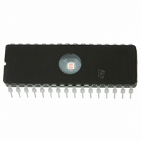
... M27C1001 1 Summary description The M27C1001 Mbit EPROM offered in the two ranges: UV (ultra violet erase) and OTP (one time programmable ideally suited for microprocessor systems requiring large programs and is organized as 131,072 words of 8 bits. The FDIP32W (window ceramic frit-seal package) has a transparent lid that enables the user to expose the chip to ultraviolet light to erase the bit pattern ...
Page 3
... Minimum DC voltage on Input or Output is –0.5V with possible undershoot to –2.0V for a period less than 20ns. Maximum DC voltage on Output is VCC +0.5V with possible overshoot to VCC +2V for a period less than 20ns. 12/24 (1) Parameter (2) M27C1001 Value Unit –40 to 125 °C –50 to 125 °C –65 to 150 ° ...
Page 4
... M27C1001 4 DC and AC characteristics 70°C, –40 to 85°C or –40 to 125° Table 5. Read Mode DC Characteristics Symbol I Input Leakage Current LI I Output Leakage Current LO I Supply Current CC I Supply Current (Standby) TTL CC1 I Supply Current (Standby) CMOS E > V CC2 I Program Current PP V Input Low Voltage ...
Page 5
... High Speed High Speed 3V 0V Standard 2.4V 0.4V 1.3V 1N914 3.3k DEVICE UNDER TEST 30pF for High Speed 100pF for Standard C L includes JIG capacitance M27C1001 Min Max = Standard 10ns 20ns 0.4V to 2.4V 1.5V 0.8V and 2V 1.5V 2.0V 0.8V AI01822 OUT ...
Page 6
... V must be applied simultaneously with or before Speed obtained with High Speed AC measurement conditions. 3. Sampled only, not 100% tested. CC (1) Test Parameter -35 Condition Min. Max. Min. Max. Min. Max. Min. Max and AC characteristics = 5V ± ± 10 M27C1001 (2) -45 - and removed simultaneously or after -70 Unit ...
Page 7
... CC (1) Test Parameter Condition Min Max Min Max Min Max Min Max and removed simultaneously or after V PP VALID tAVQV tGLQV tELQV = 5V ± ± 10 M27C1001 -12/-15/ -80 -90 -10 -20/- 100 80 90 100 VALID tAXQX tEHQZ tGHQZ M27C1001 CC Unit 120 ns 120 Hi-Z AI00713B ...
Page 8
... M27C1001 ° 6.25V ± 0.25V Table 11. Programming Mode AC Characteristics Symbol Alt t t AVPL QVPL VPHPL VPS t t VCHPL VCS t t ELPL CES t t PLPH PHQX QXGL OES t t GLQV OE ( GHQZ DFP t t GHAX must be applied simultaneously with or before Sampled only, not 100% tested. ...
Page 9
... M27C1001 5.2 32-pin Plastic DIP, 600 mils width (PDIP32) Figure 11. PDIP32 package outline Table 13. PDIP32 package mechanical data Symbol millimeters Min Typ Max 4.83 0.38 3.81 0.41 0.53 1.14 1.65 0.23 0.38 41.78 42.29 38.10 15.24 2.54 15.24 15.88 13.46 13.97 1 ...
Page 10
... High Speed, see AC Characteristics section for further information. For a list of available options (Speed, Package, etc...) or for further information on any aspect of this device, please contact the STMicroelectronics Sales Office nearest to you. 22/24 M27C1001 -10 = 100 ns -12 = 120 ns -15 = 150 ns -20 = 200 ns -25 = 250 PLCC32 N = TSOP32 M27C1001 - ...