M27C1001-12F6 STMicroelectronics, M27C1001-12F6 Datasheet
M27C1001-12F6
Specifications of M27C1001-12F6
Available stocks


Related parts for M27C1001-12F6


M27C1001-12F6 Summary of contents
Page 1
... Access Time: 35ns Low Power Consumption: – Active Current MHz – Standby Current: 100 µA Programming Voltage: 12.75V ± 0.25V Programming Time: 100 µs/word Electronic Signature – Manufacturer Code: 20h – Device Code: 05h ECOPACK® packages available M27C1001 FDIP32W (F) PDIP32 (B) PLCC32 (C) TSOP32 ( ...
Page 2
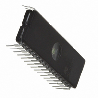
... M27C1001 1 Summary description The M27C1001 Mbit EPROM offered in the two ranges: UV (ultra violet erase) and OTP (one time programmable ideally suited for microprocessor systems requiring large programs and is organized as 131,072 words of 8 bits. The FDIP32W (window ceramic frit-seal package) has a transparent lid that enables the user to expose the chip to ultraviolet light to erase the bit pattern ...
Page 3
... Minimum DC voltage on Input or Output is –0.5V with possible undershoot to –2.0V for a period less than 20ns. Maximum DC voltage on Output is VCC +0.5V with possible overshoot to VCC +2V for a period less than 20ns. 12/24 (1) Parameter (2) M27C1001 Value Unit –40 to 125 °C –50 to 125 °C –65 to 150 ° ...
Page 4
... M27C1001 4 DC and AC characteristics 70°C, –40 to 85°C or –40 to 125° Table 5. Read Mode DC Characteristics Symbol I Input Leakage Current LI I Output Leakage Current LO I Supply Current CC I Supply Current (Standby) TTL CC1 I Supply Current (Standby) CMOS E > V CC2 I Program Current PP V Input Low Voltage ...
Page 5
... High Speed High Speed 3V 0V Standard 2.4V 0.4V 1.3V 1N914 3.3k DEVICE UNDER TEST 30pF for High Speed 100pF for Standard C L includes JIG capacitance M27C1001 Min Max = Standard 10ns 20ns 0.4V to 2.4V 1.5V 0.8V and 2V 1.5V 2.0V 0.8V AI01822 OUT ...
Page 6
... V must be applied simultaneously with or before Speed obtained with High Speed AC measurement conditions. 3. Sampled only, not 100% tested. CC (1) Test Parameter -35 Condition Min. Max. Min. Max. Min. Max. Min. Max and AC characteristics = 5V ± ± 10 M27C1001 (2) -45 - and removed simultaneously or after -70 Unit ...
Page 7
... CC (1) Test Parameter Condition Min Max Min Max Min Max Min Max and removed simultaneously or after V PP VALID tAVQV tGLQV tELQV = 5V ± ± 10 M27C1001 -12/-15/ -80 -90 -10 -20/- 100 80 90 100 VALID tAXQX tEHQZ tGHQZ M27C1001 CC Unit 120 ns 120 Hi-Z AI00713B ...
Page 8
... M27C1001 ° 6.25V ± 0.25V Table 11. Programming Mode AC Characteristics Symbol Alt t t AVPL QVPL VPHPL VPS t t VCHPL VCS t t ELPL CES t t PLPH PHQX QXGL OES t t GLQV OE ( GHQZ DFP t t GHAX must be applied simultaneously with or before Sampled only, not 100% tested. ...
Page 9
... FDIPW-a inches Min Typ 0.020 0.154 0.153 0.016 0.057 0.009 1.643 1.500 0.100 0.600 0.514 0.590 0.637 0.125 32 0.060 0.280 4° M27C1001 Max 0.225 0.055 0.180 0.177 0.022 0.012 1.655 0.526 0.710 0.161 0.098 11° ...
Page 10
... High Speed, see AC Characteristics section for further information. For a list of available options (Speed, Package, etc...) or for further information on any aspect of this device, please contact the STMicroelectronics Sales Office nearest to you. 22/24 M27C1001 -10 = 100 ns -12 = 120 ns -15 = 150 ns -20 = 200 ns -25 = 250 PLCC32 N = TSOP32 M27C1001 - ...