M27C2001-10F1 STMicroelectronics, M27C2001-10F1 Datasheet
M27C2001-10F1
Specifications of M27C2001-10F1
Available stocks


Related parts for M27C2001-10F1


M27C2001-10F1 Summary of contents
Page 1
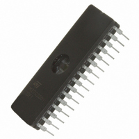
... Active Current 30mA at 5MHz – Standby Current 100µA Programming voltage: 12.75V ± 0.25V Programming time: 100µs/word Electronic signature – Manufacturer Code: 20h – Device Code: 61h Packages ® – ECOPACK packages available. M27C2001 FDIP32W (F) PDIP32 (B) PLCC32 (C) TSOP32 ( 1/25 ...
Page 2
... Summary description 1 Summary description The M27C2001 is a high speed 2 Mbit EPROM offered in the two ranges UV (ultra violet erase) and OTP (one time programmable ideally suited for microprocessor systems requiring large programs and is organized as 262,144 by 8 bits. The FDIP32W (window ceramic frit-seal package) has a transparent lids which allow the user to expose the chip to ultraviolet light to erase the bit pattern ...
Page 3
... M27C2001 3 Maximum ratings Except for the rating "Operating Temperature Range", stresses above those listed in the Table 4 may cause permanent damage to the device. These are stress ratings only and operation of the device at these or any other conditions above those indicated in the Operating sections of this specification is not implied. Exposure to Absolute Maximum Rating conditions for extended periods may affect device reliability ...
Page 4
... Sampled only, not 100% tested Figure 6. AC Testing Input Output Waveform 13/25 High Speed ( 25° MHz) A Parameter Test Condition OUT High Speed 3V 0V Standard 2.4V 0.4V M27C2001 Standard 10ns 20ns 0.4V to 2.4V 1.5V 0.8V and 2V Min Max = 1.5V 2.0V 0.8V AI01822 Unit pF pF ...
Page 5
... M27C2001 Figure 7. AC Testing Load Circuit Table 7. Read Mode DC Characteristics ( 70°C or –40 to 85° Symbol Parameter I Input Leakage Current LI I Output Leakage Current LO I Supply Current CC I Supply Current (Standby) TTL CC1 I Supply Current (Standby) CMOS CC2 I Program Current PP V Input Low Voltage ...
Page 6
... Test Condition 2.1mA –400µA OH and removed simultaneously or after ± ± 10 Test (2) -55 Condition Min Max Min and removed simultaneously or after V PP M27C2001 Min Max ± –0.3 0 0.5 CC 0.4 2.4 11.5 12 M27C2001 -70 -80 -90 Max Min Max Min Max Unit µ Unit ...
Page 7
... Chip Enable Low IL to Output Valid Output Enable IL Low to Output Valid Chip Enable IL High to Output Hi Output Enable IL High to Output Hi Address IL Transition to Output Transition PP DC and AC parameters = M27C2001 -10 -12 -15/-20/-25 Min Max Min Max Min 100 120 IL 100 120 and removed simultaneously or after V Unit ...
Page 8
... Output Enable High to Address Transition GHAX must be applied simultaneously with or before Sampled only, not 100% tested. 17/25 VALID tAVQV tGLQV tELQV (1) = 12.75 ± 0.25V) PP Parameter and removed simultaneously or after V PP M27C2001 VALID tAXQX tEHQZ tGHQZ Hi-Z AI00719B Test Min Max Condition 105 ...
Page 9
... FDIPW-a M27C2001 Max 0.225 0.055 0.180 0.177 0.022 — 0.012 1.655 — — 0.526 — — 0.710 0.098 — 11° ...
Page 10
... TR = Tape & Reel Packing 1. High Speed, see AC Characteristics section for further information. 2. These speeds are replaced by the 100ns. For a list of available options (Speed, Package, etc....) or for further information on any aspect of this de-vice, please contact the STMicroelectronics Sales Office nearest to you. 23/25 M27C2001 (2) M27C2001 - ...