DS1345WP-150+ Maxim Integrated Products, DS1345WP-150+ Datasheet
DS1345WP-150+
Specifications of DS1345WP-150+


Related parts for DS1345WP-150+


DS1345WP-150+ Summary of contents
Page 1
Rev 10/10 www.maxim-ic.com FEATURES 10 years minimum data retention in the absence of external power Data is automatically protected during power loss Power supply monitor resets processor when V power loss occurs and holds processor in ...
Page 2
READ MODE The DS1345W executes a read cycle whenever Enable) and (Output Enable) are active (low). The unique address specified by the 17 address inputs defines which of the 131,072 bytes of data is to ...
Page 3
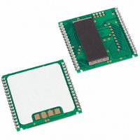
... PACKAGES The 34-pin PowerCap Module integrates SRAM memory and nonvolatile control into a module base along with contacts for connection to the lithium battery in the DS9034PC PowerCap. The PowerCap Module package design allows a DS1345W device to be surface mounted without subjecting its lithium backup battery to destructive high-temperature reflow soldering ...
Page 4
ABSOLUTE MAXIMUM RATINGS Voltage on Any Pin Relative to Ground Operating Temperature Range Commercial: Industrial: Storage Temperature Range Lead Temperature (soldering, 10s) Soldering Temperature (reflow) This is a stress rating only and functional operation of the device at these or ...
Page 5
AC ELECTRICAL CHARACTERISTICS PARAMETER Read Cycle Time Access Time to Output Valid OE to Output Valid Output Active OE CE Output High Z from Deselection Output Hold from Address Change Write Cycle Time Write Pulse Width Address ...
Page 6
WRITE CYCLE 1 SEE NOTES AND 12 WRITE CYCLE 2 SEE NOTES AND DS1345W ...
Page 7
POWER-DOWN/POWER-UP CONDITION BATTERY WARNING DETECTION SEE NOTE DS1345W ...
Page 8
POWER-DOWN/POWER-UP TIMING PARAMETER V Fail Detect to and CE CC Inactive WE V slew from Fail Detect to RST CC Active V slew from Valid to and CE ...
Page 9
... Output: 1.5V Input pulse Rise and Fall Times: 5ns ORDERING INFORMATION PART DS1345WP-100+ DS1345WP-100IND+ + Denote sa lead(Pb)-free/RoHS-compliant package. * DS9034PC+ or DS9034PCI+ (PowerCap) required. Must be ordered separately. PACKAGE INFORMATION For the latest package outline information and land patterns www.maxim-ic.com/packages. that a “+”, “#”, or “-” in the package code indicates RoHS status only. Package drawings may show a different suffix character, but the drawing pertains to the package regardless of RoHS status ...
Page 10
... Maxim cannot assume responsibility for use of any circuitry other than circuitry entirely embodied in a Maxim product. No circuit patent licenses are implied. Maxim reserves the right to change the circuitry and specifications without notice at any time © 2010 Maxim Integrated Products DESCRIPTION Maxim and the Dallas logo are registered trademarks of Maxim Integrated Products, Inc. DS1345W PAGES CHANGED ...