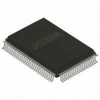
EPC16QC100N Altera, EPC16QC100N Datasheet - Page 13

EPC16QC100N
Manufacturer Part Number
EPC16QC100N
Description
IC CONFIG DEVICE 16MBIT 100-PQFP
Manufacturer
Altera
Series
EPCr
Datasheet
1.EPC8QC100.pdf
(34 pages)
Specifications of EPC16QC100N
Programmable Type
In System Programmable
Memory Size
16Mb
Voltage - Supply
3 V ~ 3.6 V
Operating Temperature
0°C ~ 70°C
Package / Case
100-MQFP, 100-PQFP
Lead Free Status / RoHS Status
Lead free / RoHS Compliant
Other names
544-1681
Available stocks
Company
Part Number
Manufacturer
Quantity
Price
Company:
Part Number:
EPC16QC100N
Manufacturer:
ALTERA30
Quantity:
660
Part Number:
EPC16QC100N
Manufacturer:
ALTERA/阿尔特拉
Quantity:
20 000
Chapter 1: Enhanced Configuration Devices (EPC4, EPC8, and EPC16) Data Sheet
Functional Description
External Flash Interface
© December 2009 Altera Corporation
f
f
Table 1–5
enhanced configuration device.
Table 1–5. Enhanced Configuration Devices in PS Mode
For configuration schematics and more information about concurrent configurations,
refer to the appropriate FPGA family chapter in the
The enhanced configuration devices support external FPGA or processor access to its
flash memory. The unused portions of the flash memory can be used by the external
device to store code or data. This interface can also be used in systems that implement
remote configuration capabilities. Configuration data within a particular
configuration page can be updated via the external flash interface and the system
could be reconfigured with the new FPGA image. This interface is also useful to store
Nios boot code, application code, or both.
For more information about the Stratix remote configuration feature, refer to the
Remote System Configuration with Stratix & Stratix GX Devices
Device Handbook.
The address, data, and control ports of the flash memory are internally connected to
the enhanced configuration device controller and to external device pins. An external
source can drive these external device pins to access the flash memory when the flash
interface is available.
This external flash interface is a shared bus interface with the configuration controller
chip. The configuration controller is the primary bus master. Since there is no bus
arbitration support, the external device can only access the flash interface when the
controller has tri-stated its internal interface to the flash. Simultaneous access by the
controller and the external device will cause contention, and result in configuration
and programming failures.
Since the internal flash interface is directly connected to the external flash interface
pins, controller flash access cycles will toggle the external flash interface pins. The
external device must be able to tri-state its flash interface during these operations and
ignore transitions on the flash interface pins.
Passive serial mode
Multi-device passive
serial mode
Multi-device passive
serial mode
Multi-device passive
serial mode
Note to
(1) This is the number of valid DATA outputs for each configuration mode.
Mode Name
Table
summarizes the concurrent PS configuration modes supported in the
1–5:
Mode (n =)
1
2
4
8
(1)
DATA0
DATA[1..0]
DATA[3..0]
DATA[7..0]
Used Outputs
Configuration Handbook (Complete Two-Volume Set)
Configuration
DATA[7..1] drive low
DATA[7..2] drive low
DATA[7..4] drive low
chapter in the Stratix
Handbook.
Unused Outputs
—
1–13


