DS1212Q Maxim Integrated Products, DS1212Q Datasheet
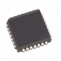
IC CONTROLLER NV 16-CHIP 28-PLCC

DS1212Q

Manufacturer Part Number
DS1212Q
Description
IC CONTROLLER NV 16-CHIP 28-PLCC
Manufacturer
Maxim Integrated Products
Datasheet

Specifications of DS1212Q

Controller Type
Nonvolatile RAM
Voltage - Supply
4.75 V ~ 5.5 V
Operating Temperature
0°C ~ 70°C
Package / Case
28-LCC, 28-PLCC
Lead Free Status / RoHS Status
Contains lead / RoHS non-compliant

Available stocks

Company
Part Number
Manufacturer
Quantity
Price
Part Number:
DS1212Q
Manufacturer:
Maxim Integrated
Quantity:
10 000
Part Number:
DS1212Q
Manufacturer:
DALLAS
Quantity:
20 000
Part Number:
DS1212QN
Manufacturer:
Maxim Integrated
Quantity:
10 000
FEATURES
PIN DESCRIPTION
A, B, C, D
GND
V
V
TOL
V
V
DESCRIPTION
The DS1212 Nonvolatile Controller x16 Chip is a CMOS circuit that solves the application problem of
converting CMOS RAMs into nonvolatile memories. Incoming power is monitored for an out-of-
tolerance condition. When such a condition is detected, the chip enables are inhibited to accomplish write
protection and the battery is switched on to supply the RAMs with uninterrupted power. Special circuitry
uses a low-leakage CMOS process that affords precise voltage detection at extremely low battery
consumption.
www.dalsemi.com
CE
CE0
PF
BAT1
BAT2
CCI
CCO
Converts full CMOS RAM into nonvolatile
memory
Unconditionally write protects when V
out of tolerance
Automatically switches to battery when
power-fail occurs
4 to 16 decoder provides control for up to 16
CMOS RAMs
Consumes less than 100 nA of battery
current
Tests battery condition on power-up
Provides for redundant batteries
Power fail signal can be used to interrupt
processor on power failure
Optional 5% or 10% power-fail detection
Optional 28-pin PLCC surface mount
package
Optional industrial temperature range of
-40°C to +85°C
-
CE15
- Address Inputs
- Chip Enable
- Chip Enable Outputs
- Ground
- + Battery 1
- + Battery 2
- Power Supply Tolerance
- +5V Supply
- RAM Supply
- Power Fail
CC
is
Nonvolatile Controller x 16 Chip
1 of 7
PIN ASSIGNMENT
CE15
CE14
CE13
CE12
CE11
VBAT1
VCCO
CE15
CE14
CE13
CE12
CE11
GND
D
TOL
C
See Mech. Drawings Section
PF
See Mech. Drawings Section
D
C
B
A
5
6
8
9
7
10
11
28-Pin DIP (600-mil)
4
12
13
1
10
11
12
13
14
2
3
5
6
7
8
9
4
3
28-Pin PLCC
14
2
15
1
28
16
28
27
26
25
24
23
22
20
19
18
17
16
15
27
17
21
26
18
25
24
23
22
21
20
19
VCCI
VBAT2
CE
CE0
CE1
CE2
CE3
CE4
CE5
CE6
CE7
CE8
CE9
CE10
CE0
CE1
CE3
CE4
CE2
CE5
CE6
DS1212
111899

Related parts for DS1212Q

DS1212Q Summary of contents

Page 1

FEATURES Converts full CMOS RAM into nonvolatile memory Unconditionally write protects when V out of tolerance Automatically switches to battery when power-fail occurs decoder provides control for CMOS RAMs Consumes less than 100 ...

Page 2

By combining the DS1212 Nonvolatile Controller chip and lithium batteries, nonvolatile RAM operation can be achieved for CMOS memories. OPERATION The DS1212 performs six circuit functions required to decode and battery back up a bank of up ...

Page 3

NONVOLATILE CONTROLLER/DECODER Figure 1 INPUTS CE0 ...

Page 4

ABSOLUTE MAXIMUM RATINGS* Voltage on Any Pin Relative to Ground Operating Temperature Storage Temperature Soldering Temperature * This is a stress rating only and functional operation of the device at these or any other conditions above those indicated in the ...

Page 5

CAPACITANCE PARAMETER Input Capacitance Output Capacitance AC ELECTRICAL CHARACTERISTICS PARAMETER Propagation Delay CE High to Power-Fail CE Address Setup PARAMETER Recovery at Power-Up V Slew Rate Power-Down CC V Slew Rate Power-Down CC V Slew Rate Power-Up CC Pulse Width ...

Page 6

TIMING DIAGRAM: DECODER TIMING DIAGRAM: POWER-UP TIMING DIAGRAM: POWER-DOWN DS1212 ...

Page 7

TYPICAL APPLICATION Figure 2 OUTPUT LOAD Figure 3 NOTES: 1. All voltages referenced to ground. 2. Only one battery input is required. 3. Measured with V and CE0 CCO the maximum average load which the DS1212 can ...

Related keywords