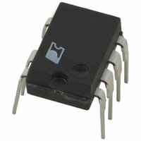
LNK520PN Power Integrations, LNK520PN Datasheet - Page 5

LNK520PN
Manufacturer Part Number
LNK520PN
Description
IC SWIT OCP CV/CC HV 8DIP
Manufacturer
Power Integrations
Series
LinkSwitch®r
Datasheet
1.LNK520PN.pdf
(20 pages)
Specifications of LNK520PN
Output Isolation
Isolated
Frequency Range
24 ~ 49.5kHz
Voltage - Output
700V
Power (watts)
4W
Operating Temperature
-40°C ~ 150°C
Package / Case
8-DIP (0.300", 7.62mm), 7 Leads
Output Voltage
5.6 V
Input / Supply Voltage (max)
265 VAC
Input / Supply Voltage (min)
85 VAC
Duty Cycle (max)
80 %
Switching Frequency
42 KHz
Supply Current
0.75 mA
Operating Temperature Range
- 40 C to + 150 C
Mounting Style
Through Hole
For Use With
596-1006 - KIT DESIGN ACCELERATOR ADAPTER596-1001 - KIT DESIGN ACCELERATOR ADAPTER
Lead Free Status / RoHS Status
Lead free / RoHS Compliant
Other names
596-1033-5
Available stocks
Company
Part Number
Manufacturer
Quantity
Price
Company:
Part Number:
LNK520PN
Manufacturer:
POWER
Quantity:
15 000
Part Number:
LNK520PN
Manufacturer:
POWER
Quantity:
20 000
Figure 7. Influence of the Optocoupler on the Power Supply Output Characteristic.
Figure 8. Output Characteristic with Optocoupler Regulation (Reduced Voltage Feedback Threshold).
is the characteristic seen if the voltage feedback threshold is
above the output voltage at the inherent CC to CV transition
point also indicated in Figure 7.
Figure 8 shows a case where the voltage feedback threshold
is set below the voltage at the inherent CC to CV transition
point. In this case, as the output voltage rises, the secondary
feedback circuit takes control before the inherent CC to CV
transition occurs. In an actual battery charging application, this
simply limits the output voltage to a lower value. However, in
laboratory bench tests, it is often more convenient to test the
power supply output characteristic starting from a low output
current and gradually increasing the load. In this case, the
threshold
feedback
Voltage
threshold
feedback
Voltage
Output Voltage
Output Voltage
Load variation
during battery
Load variation
charging
during battery
charging
transition
CC to CV
Inherent
transition
CC to CV
Output Current
point
Inherent
point
optocoupler feedback regulates the output voltage until the
peak output power curve is reached as shown in Figure 8. Under
these conditions, the output current will continue to rise until the
peak power point is reached and the optocoupler turns off. Once
the optocoupler is off, the CONTROL pin feedback current is
determined only by R1 and the output current therefore folds
back to the inherent CC characteristic as shown. Since this type
of load transition does not normally occur in a battery charger,
the output current never overshoots the inherent constant current
value in the actual application.
In some applications it may be necessary to avoid any output
current overshoot, independent of the direction of load variation.
load variation often applied during
Characteristic observed with
Output Current
laboratory bench testing
V
O(MAX)
characteristic without
without optocoupler
Tolerance envelope
Characteristic with
Typical inherent
optocoupler
optocoupler
characteristic without
without optocoupler
Tolerance envelope
output power curve
Characteristic with
Power supply peak
Typical inherent
optocoupler
optocoupler
LNK520
PI-2790-112102
PI-2788-092101
2/05
E
5


