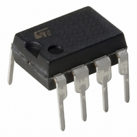
VIPER53DIP-E STMicroelectronics, VIPER53DIP-E Datasheet - Page 3

VIPER53DIP-E
Manufacturer Part Number
VIPER53DIP-E
Description
IC OFFLINE SWIT PWM CM OTP 8DIP
Manufacturer
STMicroelectronics
Series
VIPER™r
Type
Pulse Width Modulator Controllerr
Datasheets
1.VIPER53SPTR-E.pdf
(36 pages)
2.VIPER53DIP-E.pdf
(7 pages)
3.VIPER53DIP-E.pdf
(24 pages)
Specifications of VIPER53DIP-E
Output Isolation
Isolated
Frequency Range
93 ~ 300kHz
Voltage - Input
8.4 ~ 19 V
Voltage - Output
620V
Power (watts)
30W
Operating Temperature
25°C ~ 125°C
Package / Case
8-DIP (0.300", 7.62mm)
Current, Supply
9 mA
Frequency, Oscillator
100 kHz
Package Type
DIP-8
Regulator Type
Switching
Resistance, Thermal, Junction To Case
20 °C/W
Temperature, Operating, Range
-40 to +150 °C
Time, Fall
100 ns
Time, Rise
50 ns
Voltage, Supply
13 V
Power Switch Family
VIPer53DIP
Input Voltage
0 to 19V
Power Switch On Resistance
900mOhm
Output Current
1.6A
Number Of Outputs
Single
Mounting
Through Hole
Supply Current
9mA
Operating Temperature (min)
-40C
Operating Temperature (max)
150C
Operating Temperature Classification
Automotive
Pin Count
8
Mounting Style
Through Hole
For Use With
497-8435 - BOARD EVAL FOR VIPER53 28W497-6458 - BOARD EVAL BASED ON VIPER53-E497-6262 - BOARD REF SGL VIPER53 90-264VAC497-5866 - EVAL BOARD 24W NEG OUT VIPER53E
Lead Free Status / RoHS Status
Lead free / RoHS Compliant
Other names
497-6171-5
VIPer53 - E
1
1.1
1.2
Electrical data
Maximum rating
Stressing the device above the rating listed in the “Absolute Maximum Ratings” table may
cause permanent damage to the device. These are stress ratings only and operation of the
device at these or any other conditions above those indicated in the Operating sections of
this specification is not implied. Exposure to Absolute Maximum Rating conditions for
extended periods may affect device reliability. Refer also to the STMicroelectronics SURE
Program and other relevant quality documents.
Table 1.
1. In order to improve the ruggedness of the device versus eventual drain overvoltages, a resistance of 1k
Thermal data
Table 2.
1. When mounted on a standard single-sided FR4 board with 50mm² of Cu (at least 35 mm thick) connected
2. When mounted on a standard single-sided FR4 board with 50mm² of Cu (at least 35 mm thick) connected
Symbol
Symbol
I
R
R
V
I
V
T
COMP
should be inserted in series with the TOVL pin.\
to the DRAIN pin.
to the device tab.
V
V
TOVL
thJC
OSC
T
thJA
T
STG
ESD
I
DS
DD
D
C
J
Thermal Resistance Junction-case
Thermal Resistance Ambient-case
Continuous drain source voltage (T
Continuous drain current
Supply voltage
OSC input voltage range
COMP and TOVL input current range
Electrostatic discharge:
Machine model (R = 0 ; C = 200pF)
Charged device model
Junction operating temperature
Case operating temperature
Storage temperature
Absolute maximum rating
Thermal data
Parameter
Parameter
J
= 25 ... 125°C)
(1)
Max
Max
PowerSO-10
(1)
60
2
(1)
Internally limited
Internally limited
-0.3 ... 620
-40 to 150
-55 to 150
0 ... V
0 ... 19
-2 ... 2
Value
DIP-8
200
1.5
Electrical data
20
80
DD
(2)
Unit
Unit
C/W
C/W
mA
kV
V
A
V
V
V
C
C
C
3/36


