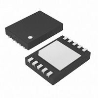
DS2710G+ Maxim Integrated Products, DS2710G+ Datasheet - Page 9

DS2710G+
Manufacturer Part Number
DS2710G+
Description
IC NIMH CHRGR SGL-CELL 10-TDFN
Manufacturer
Maxim Integrated Products
Datasheet
1.DS2710G.pdf
(12 pages)
Specifications of DS2710G+
Function
Charge Management
Battery Type
Nickel Metal Hydride (NiMH)
Voltage - Supply
4 V ~ 5.5 V
Operating Temperature
-20°C ~ 70°C
Mounting Type
Surface Mount
Package / Case
10-TDFN Exposed Pad
Lead Free Status / RoHS Status
Lead free / RoHS Compliant
TOP-OFF complete normally if the cell temperature
remains below this threshold.
Used with a 10kΩ resistor, the Semitec 103AT-2 pro-
vides approximately 0.9% full scale-per-degree sensi-
tivity. Figure 4 shows this linearity curve. The left axis is
the ratio of the sensed voltage to the divider’s input
voltage (V
The DS2710 indicates the state of charge and the
charge results on the STATUS output pin. When no cell
is present, the output is driven to a logic-low. Any LED
attached to the STATUS pin is off. When a cell is insert-
ed, STATUS oscillates in a 1Hz, 50% duty-cycle pattern
to indicate the cell is precharging. Once the DS2710
transitions to FAST-CHARGE, the STATUS output goes
to logic-high and stays high until the end of TOP-OFF.
STATUS returns to logic-low for MAINTENANCE charge
and remains at logic-low until the cell is removed or the
DS2710 is power cycled. If a FAULT occurs during
charging, STATUS toggles at a fast 4Hz, 50% duty-
cycle rate until the cell is removed. Table 2 summarizes
Table 2. LED Display Patterns Based on Charge State
Table 3. Charge-Rate Examples
FAST-CHARGE
PRECHARGE/TOP-OFF
MAINTENANCE
STATUS PIN LED
STATUS PIN
STATE
DD
).
_______________________________________________________________________________________
Charge-Status Output
NO BATTERY
Logic-low
Off
900mAH
C/1.64
C/6.37
C/102
565mA CHARGE RATE (0.200 )
AT CELL CAPACITY
Oscillates at 1Hz,
50% duty cycle
PRECHARGE
1700mAH
1Hz toggle
C/3.10
C/12.0
C/193
Single-Cell NiMH Charger
2200mAH
C/4.00
C/15.5
CHARGE STATE
C/249
the STATUS output and LED operation for each charge
condition.
The charge rate is determined by an external sense
resistor connected between the VN1 and VN0 pins. The
DS2710 regulates the charge current to maintain a volt-
age drop of V
resistor during FAST-CHARGE:
The sense resistor can therefore be selected by:
The effective FAST-CHARGE rate is equal to 0.969 times
the regulated current limit, TOP-OFF rate is 0.25 times
the regulated current, and MAINTENANCE charge rate
is 0.0156 times the regulated current. Table 3 shows
the charge rates for charging three different cell capac-
ities using a 565mA (0.200Ω sense) current source and
a 1130mA (0.100Ω sense) current source.
FAST-CHARGE/
Logic-high
V
R
TOP-OFF
SENSE
SENSE
On
= V
= 0.113V/Desired FAST-CHARGE Current
900mAH
IREF
IREF
C/0.82
C/3.19
C/51
1130mA CHARGE RATE (0.100 )
- 0.5 x V
- 0.5 x V
Charge-Rate Selection
MAINTENANCE
Logic-low
AT CELL CAPACITY
Off
HYS-COMP
HYS-COMP
1700mAH
C/1.55
C/6.0
C/96
Oscillates at 4Hz,
across the sense
= 0.113V (typ)
50% duty cycle
4Hz toggle
FAULT
2200mAH
C/7.75
C/125
C/2.0
9


