DS2756E+ Maxim Integrated Products, DS2756E+ Datasheet
DS2756E+
Specifications of DS2756E+


Related parts for DS2756E+


DS2756E+ Summary of contents
Page 1
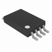
... Dimension of 8-Pin TSSOP Package Allows Mounting on Side of Thin Prismatic Li+ and Li+/Polymer Cells ORDERING INFORMATION DS2756E+ DS2756E+T&R + Denotes lead(Pb)-free/RoHS-compliant package. PIN CONFIGURATION DS2756 PART TEMP RANGE PIN-PACKAGE -20°C to +70°C 8 TSSOP DS2756E+ on -20°C to +70°C Tape-and-Reel SNS SS 2 PIO ...
Page 2
ABSOLUTE MAXIMUM RATINGS Voltage on PIO Pin, Relative to V Voltage on All Other Pins, Relative to V Continuous Sink Current, DQ, PIO Operating Temperature Range Storage Temperature Range Soldering Temperature This is a stress rating only and functional operation ...
Page 3
Period Undervoltage Detect Undervoltage Delay Internal Timebase Accuracy ELECTRICAL CHARACTERISTICS—1-WIRE INTERFACE (3.0V V 4.5V -20C to +70C PARAMETER SYMBOL Snapshot Trigger 0 Snapshot Delay STANDARD TIMING Time Slot Recovery Time Write-0 Low Time Write-1 ...
Page 4
DETAILED DESCRIPTION The DS2756 performs temperature, voltage, and current measurement to a resolution sufficient to support process- monitoring applications such as battery charge control and remaining capacity estimation. Temperature is measured using an on-chip sensor, eliminating the need for a ...
Page 5
Figure 2. Functional Diagram 1-WIRE INTERFACE DQ AND ROM ID THERMAL SENSE M U VIN X IS2 SNS DETAILED PIN DESCRIPTION Pin Name Description Battery Voltage-Sense Input. Voltage measurement performed Voltage Register. Device Ground ...
Page 6
POWER MODES The DS2756 has three power modes: Active, Suspend and Sleep. While in Active mode, the DS2756 continuously measures voltage, temperature, current, accumulated current, and monitors for an under voltage condition. In Suspend and Sleep modes, the DS2756 ceases ...
Page 7
Average Current and Accumulated Current values by the current sample timing discontinuity introduced with each trigger of the Snapshot mode, use of Snapshot once every 5s does not produce a significant error. The following ...
Page 8
ACR register address. A write to the ACR results in an automatic copy of the new value to EEPROM. Figure 5. Accumulated Current Register Format MSB-Address 10h MSb V - ...
Page 9
Figure 6. Accumulation Bias Register Format VOLTAGE MEASUREMENT The voltage register operates in two modes, normal and snapshot. In normal mode, the DS2756 continually measures the voltage between pins V two’s-complement format every 3.4ms with a resolution of 4.88mV. In ...
Page 10
PROGRAMMABLE I/O The PIO pin can be configured as a general purpose programmable I/O pin interrupt output. To use the PIO pin in the programmable I/O mode described in this section, the PIO interrupt method must not ...
Page 11
Table 1. PIO/DQ Pin Function REGISTER BIT SETTING PIE IOS IE PIO xDon’t care. ...
Page 12
ALARM COMPARATORS AND INTERRUPT THRESHOLDS Alarm interrupt threshold values can be programmed by the user in the designated SRAM memory registers in the formats and locations found in Figure 11. Since these thresholds are located in SRAM memory, they must ...
Page 13
Figure 11. Alarm Interrupt Threshold Register Formats Current Accumulator Interrupt High Threshold MSB-Address 80h MSb Current Accumulator Interrupt Low Threshold MSB-Address 82h MSb Temperature Interrupt High ...
Page 14
Figure 12. Alarm And Suspend Mode Operating Diagram IE Interrupt Enable PIE 00b Programmable Interrupt Enable Charge Suspend Interrupt Threshold CURRENT Discharge Suspend Interrupt Threshold High Temperature Interrupt Threshold TEMPERATURE Low Temperature Interrupt Threshold Note 1 High Accumulator Interrupt Threshold ...
Page 15
SNAPSHOT MODE Measurement of the current and voltage can be synchronized to a system event with the Snapshot mode. Triggering a Snapshot event causes the ADC to abandon the current conversion and capture one current and one voltage sample. The ...
Page 16
MEMORY The DS2756 has a 256-byte linear address space with registers for instrumentation, status, and control in the lower 32 bytes, with lockable EEPROM and SRAM memory occupying portions of the remaining address space. All EEPROM and SRAM memory is ...
Page 17
Table 2. Memory Map ADDRESS (HEX) 00 Reserved 01 Status Register Reserved 07 EEPROM Register 08 Special Feature Register Reserved 0C Voltage Register MSB 0D Voltage Register LSB 0E Current Register MSB 0F Current ...
Page 18
Table 3. SUMMARY OF SUSPEND MODES SAMPLE RATE WHILE IN PIE1 PIE0 SUSPEND MODE 0 0 Suspend mode disabled The desired default value should be set in bit 6 and bit 7 of address ...
Page 19
EEC—EEPROM Copy Flag this read-only bit indicates that a Copy Data command is in progress. While this bit is high, writes to EEPROM addresses are ignored this bit indicates that data can be written ...
Page 20
BUS SYSTEM The 1-Wire bus is a system that has a single bus master and one or more slaves. A multidrop bus is a 1-Wire bus with multiple slaves. A single-drop bus has only one slave device. In all ...
Page 21
If the bus is left low for more than 120s, slave devices on the bus begin to interpret the low period as a reset pulse, effectively terminating the transaction. Figure 20. Typical 1-Wire Bus Interface Circuitry BUS MASTER Rx ...
Page 22
This command can be used with one or more slave devices on the bus. Skip Net Address [CCh]. This command saves time when there is only one DS2756 on the bus ...
Page 23
Table 4. FUNCTION COMMANDS COMMAND DESCRIPTION Reads data from memory Read Data starting at address XX Writes data to memory Write Data starting at address XX Copies shadow RAM data to Copy Data EEPROM block containing address XX Recalls EEPROM ...
Page 24
Figure 21. Net Address Command Flow Chart ...
Page 25
I/O SIGNALING The 1-Wire bus requires strict signaling protocols to ensure data integrity. The four protocols or signaling types used are: 1) Initialization sequence (Reset Pulse followed by Presence Pulse) 2) Write 0 3) Write 1 4) Read Data All ...
Page 26
Figure 23. 1-Wire Write- And Read-Time Slots WRITE 0 SLOT V PULLUP GND DS2756 Sample Window Mode MIN Standard 15s 15s Overdrive 2s 1s READ 0 SLOT V PULLUP GND t RDV LINE TYPE LEGEND: BUS MASTER ACTIVE LOW BOTH ...
Page 27
... Maxim/Dallas Semiconductor reserves the right to change the circuitry and specifications without notice at any time The Maxim logo is a registered trademark of Maxim Integrated Products, Inc. The Dallas logo is a registered trademark of Dallas Semiconductor Corporation. DESCRIPTION maximum operating range in the DD voltage” ...