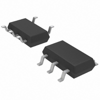
LTC4054LES5-4.2#TRM Linear Technology, LTC4054LES5-4.2#TRM Datasheet - Page 12

LTC4054LES5-4.2#TRM
Manufacturer Part Number
LTC4054LES5-4.2#TRM
Description
IC CHARGR BATTERY L-ION TSOT23-5
Manufacturer
Linear Technology
Datasheet
1.LTC4054LES5-4.2TRPBF.pdf
(16 pages)
Specifications of LTC4054LES5-4.2#TRM
Function
Charge Management
Battery Type
Lithium-Ion (Li-Ion)
Voltage - Supply
4.25 V ~ 6.5 V
Operating Temperature
-40°C ~ 85°C
Mounting Type
Surface Mount
Package / Case
SOT-23-5 Thin, TSOT-23-5
Lead Free Status / RoHS Status
Contains lead / RoHS non-compliant
Other names
LTC4054LES5-4.2
LTC4054LES5-4.2
LTC4054LES5-4.2
Available stocks
Company
Part Number
Manufacturer
Quantity
Price
Part Number:
LTC4054LES5-4.2#TRMLTC4054LES5-4.2#25221
Manufacturer:
LINEAR/凌特
Quantity:
20 000
APPLICATIO S I FOR ATIO
LTC4054L-4.2
Example: An LTC4054L operating from a 6V wall adapter
is programmed to supply 150mA full-scale current to a
discharged Li-Ion battery with a voltage of 3.75V. Assum-
ing
LTC4054L will begin to reduce the charge current is
approximately:
The LTC4054L can be used above 52.5 C, but the charge
current will be reduced from 150mA. The approximate
current at a given ambient temperature can be approxi-
mated by:
Using the previous example with an ambient tempera-
ture of 60 C, the charge current will be reduced to
approximately:
Moreover, when thermal feedback reduces the charge
current, the voltage at the PROG pin is also reduced
proportionally as discussed in the Operation section.
It is important to remember that LTC4054L applications
do not need to be designed for worst-case thermal condi-
tions since the IC will automatically reduce power dissipa-
tion when the junction temperature reaches approximately
120 C.
12
T
T
T
I
I
I
BAT
BAT
BAT
A
A
A
JA
= 120 C – (6V – 3.75V) • (150mA) • 200 C/W
= 120 C – 0.3375W • 200 C/W = 120 C – 67.5 C
= 52.5 C
is 200 C/W, the ambient temperature at which the
133
V
6
CC
V
120
mA
– .
–
120
3 75
V
BAT
C T
U
C
–
V
–
A
•
•
60
200
U
JA
C
C W
/
W
450
60
C A
C
/
U
Thermal Considerations
Because of the small size of the ThinSOT package, it is very
important to use a good thermal PC board layout to
maximize the available charge current. The thermal path
for the heat generated by the IC is from the die to the
copper lead frame, through the package leads, (especially
the ground lead) to the PC board copper. The PC board
copper is the heat sink. The footprint copper pads should
be as wide as possible and expand out to larger copper
areas to spread and dissipate the heat to the surrounding
ambient. Feedthrough vias to inner or backside copper
layers are also useful in improving the overall thermal
performance of the charger. Other heat sources on the
board, not related to the charger, must also be considered
when designing a PC board layout because they will affect
overall temperature rise and the maximum charge current.
The following table lists thermal resistance for several
different board sizes and copper areas. All measurements
were taken in still air on 3/32" FR-4 board with the device
mounted on topside.
Table 1. Measured Thermal Resistance (2-Layer Board*)
*Each layer uses one ounce copper
Table 2. Measured Thermal Resistance (4-Layer Board**)
**Top and bottom layers use two ounce copper, inner layers use one
***10,000mm
ounce copper.
2500mm
1000mm
TOPSIDE
225mm
100mm
50mm
COPPER AREA
COPPER AREA
(EACH SIDE)
2500mm
2
2
2
2
2
2
BACKSIDE
total copper area
2500mm
2500mm
2500mm
2500mm
2500mm
2***
2
2
2
2
2
2500mm
2500mm
2500mm
2500mm
2500mm
2500mm
BOARD
BOARD
AREA
AREA
2
2
2
2
2
2
JUNCTION-TO-AMBIENT
JUNCTION-TO-AMBIENT
THERMAL RESISTANCE
THERMAL RESISTANCE
125 C/W
125 C/W
130 C/W
135 C/W
150 C/W
80 C/W
4054l42f


