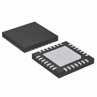
LTC4066EPF#TRPBF Linear Technology, LTC4066EPF#TRPBF Datasheet - Page 23

LTC4066EPF#TRPBF
Manufacturer Part Number
LTC4066EPF#TRPBF
Description
IC USB POWER MANAGER 24-UTQFN
Manufacturer
Linear Technology
Datasheet
1.LTC4066EUFPBF.pdf
(28 pages)
Specifications of LTC4066EPF#TRPBF
Function
Power Management
Battery Type
Lithium-Ion (Li-Ion)
Voltage - Supply
4.35 V ~ 5.5 V
Operating Temperature
-40°C ~ 85°C
Mounting Type
Surface Mount
Package / Case
24-UFQFN Exposed Pad
Lead Free Status / RoHS Status
Lead free / RoHS Compliant
Available stocks
Company
Part Number
Manufacturer
Quantity
Price
APPLICATIONS INFORMATION
Current Limit Undervoltage Lockout
An internal undervoltage lockout circuit monitors the
input voltage and disables the input current limit circuits
until V
The current limit UVLO circuit has a built-in hysteresis of
125mV. Furthermore, to protect against reverse current in
the power MOSFET, the current limit UVLO circuit disables
the current limit (i.e., forces the input power path to a high
impedance state) if V
UVLO comparator is tripped, the current limit circuits will
not come out of shutdown until V
the V
Charger Undervoltage Lockout
An internal undervoltage lockout circuit monitors the V
voltage and disables the battery charger circuits until
V
battery charger UVLO circuit has a built-in hysteresis of
125mV. Furthermore, to protect against reverse current
in the power MOSFET, the charger UVLO circuit keeps the
charger shutdown if V
comparator is tripped, the charger circuits will not come
out of shutdown until V
Shutdown
The LTC4066/LTC4066-1 can be shutdown by forcing the
SHDN pin greater than 1.2V. In shutdown, the currents
drawn from IN, OUT and BAT are decreased to less than
2.5μA and the internal battery charge timer and end-of-
charge comparator output are reset. All power paths are
put in a high impedance state.
OUT
IN
rises above the undervoltage lockout threshold. The
IN
voltage.
rises above the undervoltage lockout threshold.
BAT
OUT
OUT
exceeds V
exceeds V
exceeds V
OUT
OUT
IN
. If the charger UVLO
. If the current limit
BAT
falls 50mV below
by 50mV.
OUT
Suspend
The LTC4066/LTC4066-1 can be put in suspend mode by
forcing the SUSP pin greater than 1.2V. In suspend mode
the ideal diode function from BAT to OUT is kept alive.
If power is applied to the OUT pin externally (i.e., a wall
adapter is present) then charging will be unaffected. Current
drawn from the IN pin is reduced to 50μA. Suspend mode
is intended to comply with the USB Power Specifi cation
mode of the same name.
Selecting WALL Input Resistors
The WALL input pin identifi es the presence of a wall adapter.
This information is used to disconnect the input pin, IN,
from the OUT pin in order to prevent back conduction to
whatever may be connected to the input. It also forces the
ACPR pin low when the voltage at the WALL pin exceeds
the input threshold. The WALL pin has a 1.225V rising
threshold and approximately 30mV of hysteresis.
The wall adapter detection threshold is set by the follow-
ing equation:
where V
V
R1 is the resistor from the wall adapter input to WALL and
R2 is the resistor from WALL to GND.
WALL
V
V
HYST
TH
is the WALL pin rising threshold (typically 1.225V),
(
TH
Adapter
(
(Adapter) is the wall adapter detection threshold,
Adapter
)
LTC4066/LTC4066-1
=
)
V
=
WALL
V
WALL HYST
•
⎛
⎜
⎝
(
1
+
R
R
)
2
1
•
⎞
⎟
⎠
⎛
⎜
⎝
1
+
R
R
2
1
⎞
⎟
⎠
23
4066fc


