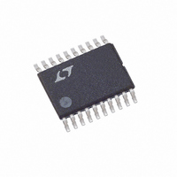
LTC4011CFE Linear Technology, LTC4011CFE Datasheet - Page 16

LTC4011CFE
Manufacturer Part Number
LTC4011CFE
Description
IC BATT CHARGER HIEFF 20TSSOP
Manufacturer
Linear Technology
Datasheet
1.LTC4011CFEPBF.pdf
(26 pages)
Specifications of LTC4011CFE
Function
Charge Management
Battery Type
Nickel Cadmium (NiCd), Nickel Metal-Hydride (NiMH)
Voltage - Supply
4.5 V ~ 34 V
Operating Temperature
0°C ~ 85°C
Mounting Type
Surface Mount
Package / Case
20-TSSOP (0.173", 4.40mm Width) Exposed Pad
Lead Free Status / RoHS Status
Contains lead / RoHS non-compliant
Available stocks
Company
Part Number
Manufacturer
Quantity
Price
Part Number:
LTC4011CFE
Manufacturer:
LINEAR/凌特
Quantity:
20 000
Part Number:
LTC4011CFE#PBF
Manufacturer:
LINEAR/凌特
Quantity:
20 000
LTC4011
applicaTions inForMaTion
Programming Maximum Charge Times
Connecting the appropriate resistor between the TIMER
pin and GND programs the maximum duration of various
charging states. To some degree, the value should reflect
how closely the programmed charge current matches the
1C rate of targeted battery packs. The maximum fast charge
period is determined by the following equation:
Some typical timing values are detailed in Table 3. R
should not be less than 15k. The actual time limits used
by the LTC4011 have a resolution of approximately ±30
seconds in addition to the tolerances given the Electrical
Characteristics table. If the timer ends without a valid –∆V or
∆T/∆t charge termination, the charger enters the fault state.
The maximum time period is approximately 4.3 hours.
Cell Voltage Network Design
An external resistor network is required to provide the
average single-cell voltage to the V
Table 2. LTC4011 Charging Parameters
PC: Precharge
FC: Fast Charge (Initial –∆V Termination Hold Off of t
TOC: Top-Off Charge (Only for NiMH ∆T/∆t FC Termination After Initial t
AR: Automatic Recharge (Temperature Limits Apply to State Termination Only)
Table 3. LTC4011 Time Limit Programming Examples
STATE
TOC
PC
AR
FC
R
24.9k
33.2k
49.9k
66.5k
100k
TIMER
CHEM
Open
GND
GND
PIN
TYPICAL FAST
CHARGE RATE
0.75C
1.5C
C/2
2C
1C
CHEMISTRY
NiMH
NiMH
Both
NiCd
Both
BAT
CELL
PRECHARGE LIMIT
t
(MINUTES)
TIMER
pin of the LTC4011.
MAX
t
MAX
t
t
MAX
MAX
3.8
7.5
10
15
/12
/3
5
T
5°C
5°C
5°C
5°C
5°C
MIN
MAX
/12 Minutes May Apply)
TIMER
VOLTAGE STABILIZATION
T
45°C
60°C
60°C
60°C
45°C
MAX
FAST CHARGE
(MINUTES)
MAX
3.8
7.5
10
15
The proper circuit for multicell packs is shown in Figure 3.
The ratio of R2 to R1 should be a factor of (n – 1), where
n is the number of series cells in the battery pack. The
value of R1 should be between 1k and 100k. This range
limits the sensing error caused by V
and prevents the ON resistance of the internal NFET be-
tween V
the V
used to detect battery insertion and removal. The filter
formed by C1 and the parallel combination of R1 and R2
I
5
I
PROG
PROG
I
I
I
CHRG
PROG
PROG
/12 Period)
0
/10 Timer Expires
/5
CELL
CDIV
Timer Expires
–20mV per Cell or 2°C/Minute
1.5°C/Minute for First t
V
–10mV per Cell or 1°C/Minute After t
or if Initial V
V
CELL
CELL
voltage. The external resistor network is also
Figure 3. Mulitple Cell Voltage Divider
and GND from causing a significant error in
< 1.325V
< 1.325V
FAST CHARGE LIMIT
LTC4011
CELL
(HOURS)
TERMINATION CONDITION
V
0.75
V
> 1.325V
1.5
CELL
CDIV
GND
1
2
3
BAT
12
8
9
5
MAX
4011 F03
/12 Minutes if Initial
MORE SERIES CELLS
R2
R1
R2 = R1(n – 1)
FOR TWO OR
CELL
MAX
(MINUTES)
+
TOP-OFF
CHARGE
C1
/12 Minutes
15
20
30
40
60
leakage current
4011fb


