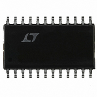
LT1511ISW Linear Technology, LT1511ISW Datasheet - Page 4

LT1511ISW
Manufacturer Part Number
LT1511ISW
Description
IC BATT CHRGR CONST I/V 3A24SOIC
Manufacturer
Linear Technology
Datasheet
1.LT1511CSWPBF.pdf
(16 pages)
Specifications of LT1511ISW
Function
Charge Management
Battery Type
Li-Ion, NiCd, NiMH
Voltage - Supply
6 V ~ 28 V
Operating Temperature
-40°C ~ 85°C
Mounting Type
Surface Mount
Package / Case
24-SOIC (0.300", 7.50mm Width)
Lead Free Status / RoHS Status
Contains lead / RoHS non-compliant
Available stocks
Company
Part Number
Manufacturer
Quantity
Price
Part Number:
LT1511ISW
Manufacturer:
LINEAR/凌特
Quantity:
20 000
Company:
Part Number:
LT1511ISW#PBF
Manufacturer:
TI
Quantity:
696
Part Number:
LT1511ISW#PBF
Manufacturer:
LINEAR/凌特
Quantity:
20 000
Company:
Part Number:
LT1511ISW#TRPBF
Manufacturer:
LT
Quantity:
3 140
Part Number:
LT1511ISW#TRPBF
Manufacturer:
LTNEAR
Quantity:
20 000
LT1511
temperature range, otherwise specifications are at T
No load on any outputs unless otherwise noted.
Note 1: Absolute Maximum Ratings are those values beyond which the life
of a device may be impaired.
Note 2: Tested with Test Circuit 1.
TYPICAL PERFORMANCE CHARACTERISTICS
ELECTRICAL CHARACTERISTICS
PARAMETER
Voltage Amplifier VA
Transconductance (Note 3)
Output Source Current
OVP Input Bias Current
Current Limit Amplifier CL1, 8V Input Common Mode
Turn-On Threshold
Transconductance
CLP Input Current
CLN Input Current
4
3.0
2.8
2.6
2.4
2.2
2.0
5
Thermally Limited Maximum
Charging Current
NOTE: FOR 4.2V AND 8.4V BATTERIES MAXIMUM
CHARGING CURRENT IS 3A FOR V
(
T
T
AMAX
JMAX
JA
=30 C/W)
10
=125 C
=60 C
4.2V BATTERY
V
IN
INPUT VOLTAGE (V)
8.4V BATTERY
V
8V
IN
15
11V
12.6V BATTERY
20
16.8V BATTERY
W
IN
25
– V
1511 • TPC01
BAT
U
30
3V
CONDITIONS
Output Current from 50 A to 500 A
V
At 0.75mA VA Output Current
At 0.75mA VA Output Current, T
0.75mA Output Current
Output Current from 50 A to 500 A
0.75mA Output Current, V
0.75mA Output Current V
100
OVP
98
96
94
92
90
88
86
84
82
80
A
0.2
Efficiency of Figure 1 Circuit
= 25 C. V
= V
V
V
IN
BAT
0.6
REF
= 16.5
The
= 8.4V
+ 10mV, V
1.0
CC
denotes specifications which apply over the full operating
INCLUDES LOSS
= 16V, V
1.4
IN DIODE D3
I
BAT
PROG
Note 3: Tested with Test Circuit 2.
Note 4: A linear interpolation can be used for reference voltage
specification between 0 C and – 40 C.
CHARGER EFFICIENCY
(A)
UV
1.8
UV
= V
BAT
0.4V
0.4V
2.2
REF
J
= 8V, V
> 90 C
+ 10mV
2.6
1511 • TPC02
MAX
3.0
(maximum operating V
8
7
6
5
4
3
2
1
0
0
I
MIN
0.25
– 15
CC
1.1
0.5
93
V
CC
vs Duty Cycle
10
= 16V
0 C
25 C
20
TYP
100
0.6
0.3
0.8
DUTY CYCLE (%)
1
3
30
CC
) = 28V.
40
125 C
MAX
107
1.3
25
2
1
2
10
50
60
1511 • TPC03
UNITS
70
mho
mho
mA
mV
mA
nA
nA
80
A


