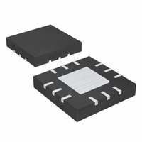
MAX6784TCA+ Maxim Integrated Products, MAX6784TCA+ Datasheet - Page 14

MAX6784TCA+
Manufacturer Part Number
MAX6784TCA+
Description
IC BATT MON TRPL .5% 12TQFN
Manufacturer
Maxim Integrated Products
Datasheet
1.MAX6782TEB.pdf
(17 pages)
Specifications of MAX6784TCA+
Function
Battery Monitor
Battery Type
Alkaline, Li-Ion, NiCd, NiMH
Voltage - Supply
1.2 V ~ 5.5 V
Operating Temperature
-40°C ~ 85°C
Mounting Type
Surface Mount
Package / Case
12-TQFN Exposed Pad
Number Of Voltages Monitored
3
Monitored Voltage
- 0.3 V to + 6 V
Undervoltage Threshold
0.5994 V, Adjustable
Overvoltage Threshold
0.6115 V, Adjustable
Output Type
Active Low, Push-Pull
Manual Reset
Not Resettable
Watchdog
No Watchdog
Battery Backup Switching
Backup
Supply Voltage (max)
5.5 V
Supply Voltage (min)
1.2 V
Supply Current (typ)
10 uA
Maximum Power Dissipation
1333 mW
Maximum Operating Temperature
+ 85 C
Mounting Style
SMD/SMT
Minimum Operating Temperature
- 40 C
Power Fail Detection
No
Lead Free Status / RoHS Status
Lead free / RoHS Compliant
For monitoring higher voltages, supply a voltage to BATT,
which is within the specified supply range, and power the
input resistive divider from the high voltage to be moni-
tored. Do not exceed the Absolute Maximum Ratings.
Since the ground connection of the MAX6782–MAX6790
has a small series resistance, any current flowing into an
output flows to ground and causes a small voltage to
develop from the internal ground to GND. This has the
effect of slightly increasing the reference voltage. To mini-
mize the effect on the reference voltage, keep the total
output sink current below 3mA.
Low-Power, 1% Accurate, Dual-/Triple-/Quad-Level
Battery Monitors in Small TDFN and TQFN Packages
Figure 6. Internal Preset or Externally Adjusted Hysteresis
Connection
14
B) EXTERNAL HYSTERESIS ADJUST CONNECTION
A) FACTORY PRESET HYSTERESIS CONNECTION
R
R
______________________________________________________________________________________
1
2
R
R
Monitoring a Battery Voltage Higher
1
2
R
R
3
4
Maintaining Reference Accuracy
IN_
REF
HADJ_
IN_
REF
HADJ_
than the Allowable V
MAX6782
MAX6783
MAX6784
MAX6785
MAX6782
MAX6783
MAX6784
MAX6785
BATT
BATT
GND
GND
1
LBO_
LBO_
BATT
If monitoring voltages in a noisy environment, add a
bypass capacitor of 0.1µF from BATT to GND as close
as possible to the device. For systems with large tran-
sients, additional capacitance may be required.
To prevent damage to the device during a reverse-battery
condition, connect the MAX6782–MAX6785 in the configu-
ration shown in Figure 6a or 6b. For the internal reverse-
battery protection to function correctly on the MAX6782–
MAX6790, several conditions must be satisfied:
• The connections to IN_/LBL_/LBH_ must be made to
• HADJ_ (MAX6782–MAX6785 only) must either be
• The outputs may only be connected to devices pow-
Note that the MAX6782–MAX6790 will not protect other
devices in the circuit.
Figure 7 shows the MAX6786/MAX6787/MAX6788 in a
typical two-battery-level monitoring circuit.
Figure 7. Two-Battery-Level Monitor Configuration
the center node of a resistive divider going from
BATT to GND. The Thevenin equivalent impedance
of the resistive divider must not fall below 1kΩ in
order to limit the current.
connected to GND or to the center node of a resis-
tive divider going from REF to GND.
ered by the same battery as the MAX6782–
MAX6790.
Adding External Capacitance to Reduce
Additional Application Circuit
Reverse-Battery Protection
LBL1
LBH1
LBL2
LBH2
Noise and Transients
MAX6786
MAX6787
MAX6788
BATT
GND
LBO1
LBO2


