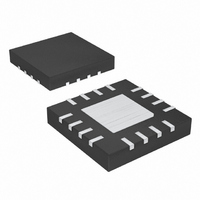
MAX1874ETE+T Maxim Integrated Products, MAX1874ETE+T Datasheet - Page 3

MAX1874ETE+T
Manufacturer Part Number
MAX1874ETE+T
Description
IC LI+ CHARGER DUAL-IN 16-TQFN
Manufacturer
Maxim Integrated Products
Datasheet
1.MAX1874ETE.pdf
(17 pages)
Specifications of MAX1874ETE+T
Function
Charge Management
Battery Type
Lithium-Ion (Li-Ion)
Voltage - Supply
4.35 V ~ 6.5 V
Operating Temperature
-40°C ~ 85°C
Mounting Type
Surface Mount
Package / Case
16-WQFN Exposed Pad
Lead Free Status / RoHS Status
Lead free / RoHS Compliant
ELECTRICAL CHARACTERISTICS (continued)
(V
noted. Typical values are at T
BATTERY CHARGING AND PRECHARGE CURRENT
DCI Voltage Range
DCI Voltage to BATT Current
USB Charging Current
Soft-Start Current-Ramp Time
Prequal Charging Current
BATT Input Current
BATT Shutdown Current
THERMISTOR MONITOR AND DIE-TEMPERATURE REGULATION
THRM COLD Trip Level
THRM HOT Trip Level
THRM Disable Threshold
Internal Die Thermal Limit
LOGIC INPUT/OUTPUTS AND GATE DRIVERS
PON High Output Resistance
PON Low Output Resistance
DCOK Low Output Resistance
DCOK Off-Leakage Current
UOK Output Resistance
UOK Off-Leakage Current
CHG Threshold to Indicate Battery Full,
Battery Current Falling (Note 3)
CHG Logic-Low Output
CHG Leakage Current
EN, USEL Logic-Input High Level
EN, USEL Logic-Input Low Level
EN, USEL Input Bias Current
USB
Li+ Charger with OVP and Thermal Regulation
= V
DC
= V
PARAMETER
DCLV
_______________________________________________________________________________________
= V
EN
= V
A
= +25°C.)
USEL
Dual-Input, USB/AC Adapter, 1-Cell
= 5V, V
V
V
USEL = high
USEL = low
Measured from 10% to 90%
V
No DC or USB power, V
EN = GND, USB- and/or DC-powered
(Note 2)
(Note 2)
PON pulled up to active input (DCLV or USB),
V
PON resistance to GND, V
DCOK pulled low
V
UOK resistance to GND, V
V
DC input (% of charge current set at DCI)
U S B i np ut, U S E L = 5V ( % of U S B char g i ng cur r ent)
USB input with USEL = 0
Sinking 10mA sink
V
DCI
DCI
BATT
DCLV
DCOK
UOK
CHG
BATT
= V
= V
= 6.5V
= 6.5V
= 2.5V
or V
= 12V, V
= 4.2V, V
REF
REF
USB
/ 2
= 5V
DC
THRM
CONDITIONS
= 0V
= V
BATT
DCLV
DC
REF
= 4.2V
= 0
/ 2, Circuit of Figure 2, T
= V
USB
= 0
0.1 x V
0.72
0.28
MIN
950
490
A
1.6
35
50
20
8
= 0°C to +85°C, unless otherwise
REF
Voltage
mode
+105
1000
TYP
0.74
0.29
12.5
520
455
100
120
82
55
25
25
25
25
7
5
1
MAX
V
1050
0.76
0.30
550
495
150
7.5
0.4
0.4
95
70
19
30
REF
2
1
1
1
1
UNITS
V
V
mA
mA
mA
mV
ms
µA
µA
kΩ
µA
µA
µA
µA
°C
REF
REF
%
Ω
Ω
Ω
V
V
V
V
3


