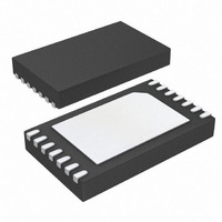
DS2784G+T&R Maxim Integrated Products, DS2784G+T&R Datasheet - Page 28

DS2784G+T&R
Manufacturer Part Number
DS2784G+T&R
Description
IC FUEL GAUGE STND-ALONE 14-TDFN
Manufacturer
Maxim Integrated Products
Datasheet
1.DS2784G.pdf
(43 pages)
Specifications of DS2784G+T&R
Function
Fuel, Gas Gauge/Monitor
Battery Type
Lithium-Ion (Li-Ion), Lithium-Polymer (Li-Pol)
Voltage - Supply
2.5 V ~ 4.6 V
Operating Temperature
-40°C ~ 85°C
Mounting Type
Surface Mount
Package / Case
14-TDFN
Lead Free Status / RoHS Status
Lead free / RoHS Compliant
Calculation of Results
SPECIAL FEATURE REGISTER FORMAT
All register bits are read and write accessible, with default values specified in each bit definition.
PIOB—PIO Pin Sense and Control Bit. Writing a 0 to the PIOB bit activates the PIO pin open-drain output driver,
forcing the PIO pin low. Writing a 1 to PIOB disables the output driver, allowing the PIO pin to be pulled high or
used as an input. Reading PIOB returns the logic level forced on the PIO pin. Note that if the PIO pin is high
impedance/unconnected with PIOB set, a weak pulldown current source pulls the PIO pin to V
on power-up. PIOB is also set in Sleep mode to ensure the PIO pin is high-impedance in sleep mode.
Note: Do not write PIOB to 0 if PSPIO is enabled.
X—Reserved Bits.
EEPROM REGISTER
The EEPROM register provides access control of the EEPROM blocks. EEPROM blocks can be locked to prevent
alteration of data within the block. Locking a block disables write access to the block. Once a block is locked, it
cannot be unlocked. Read access to EEPROM blocks is unaffected by the lock/unlock status.
EEPROM REGISTER FORMAT
EEC—EEPROM Copy Flag. A 1 in this read-only bit indicates that a Copy Data Function command is in progress.
While this bit is high, writes to EEPROM addresses are ignored. A 0 value in this bit indicates that data can be
written to unlocked EEPROM.
LOCK—EEPROM Lock Enable. When the lock bit is 0, the Lock Function command is ignored. Writing a 1 to this
bit enables the Lock Function command. After setting the lock bit the Lock Function command must be issued as
the next command, or else the lock bit is reset to 0. After the lock operation is completed, the lock bit is reset to 0.
The lock bit is a volatile R/W bit, initialized to 0 upon POR.
RAAC [mAh] = (ACR[mVh] - AE(T) * FULL40[mVh]) * R
Note: R
RSAC [mAh] = (ACR[mVh] - SE(T) * FULL40[mVh]) * R
Note: R
RARC [%] = 100% * (ACR[mVh] - AE(T) * FULL40[mVh]) /
RSRC [%] = 100%* (ACR[mVh] - SE(T) * FULL40[mVh]) /
SNSP
SNSP
BIT 7
BIT 7
EEC
= 1/R
= 1/R
X
SNS
SNS
LOCK
BIT 6
BIT 6
X
BIT 5
BIT 5
X
X
{(AS * FULL(T) - AE(T)) * FULL40[mVh]}
{(AS * FULL(T) - SE(T)) * FULL40[mVh]}
BIT 4
BIT 4
ADDRESS 15H
ADDRESS 1Fh
X
X
28 of 43
BIT 3
BIT 3
X
X
SNSP
SNSP
[mhos]
[mhos]
BIT 2
BIT 2
X
X
BIT 1
BIT 1
BL1
X
BIT 0
PIOB
BIT 0
BL0
SS
. PIOB is set to a 1


