IR2172 International Rectifier, IR2172 Datasheet - Page 3
IR2172
Manufacturer Part Number
IR2172
Description
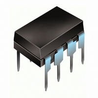
IC CURRENT SENSING LINEAR 8-DIP
Manufacturer
International Rectifier
Datasheet
1.IR2172.pdf
(7 pages)
Specifications of IR2172
Function
Current Sense
Voltage - Input
9.5 ~ 20 V
Current - Output
20mA
Operating Temperature
-40°C ~ 125°C
Mounting Type
Through Hole
Package / Case
8-DIP (0.300", 7.62mm)
Lead Free Status / RoHS Status
Contains lead / RoHS non-compliant
Accuracy
-
Sensing Method
-
Other names
*IR2172
Available stocks
Company
Part Number
Manufacturer
Quantity
Price
Company:

Part Number:
IR2172
Manufacturer:
ERICSSON
Quantity:
20
Part Number:
IR2172
Manufacturer:
IR
Quantity:
20 000
Company:
Part Number:
IR2172S
Manufacturer:
IQR
Quantity:
5 510
Part Number:
IR2172S
Manufacturer:
IR
Quantity:
20 000
Part Number:
IR2172STRPBF
Manufacturer:
IR
Quantity:
20 000


DC Electrical Characteristics
V
Note 1:
Note 2: Gain = (full range of duty cycle in %) / (full input voltage range).
www.irf.com
AC Electrical Characteristics
V
Propagation delay characteristics
Symbol
Symbol
CC
CC
V
V
G
Dmax
V
V
OS
I
Dmin
V
I
I
I
LIN
PHS
f
V
OPO
OCC
QBS
QCC
LIN
BW
I
= V
OC+
/
OC-
G
/
LK
OS
fo
IN
= V
/
/
T
T
T
A
BS
A
BS
T
A
A
10mV offset represents 1.5% duty cycle fluctuation
= 15V, unless otherwise specified.
= 15V, unless otherwise specified.
Minimum duty
Carrier frequency output
Temperature drift of carrier frequency
Maximum duty
fo bandwidth
Phase shift at 1kHz
|V
Input offset voltage temperature drift
Linearity (duty cycle deviation from ideal linearity
curve)
Linearity temperature drift
Digital PWM output sink current
OC output sink current
Nominal input voltage range before saturation
Overcurrent trip positive input voltage
Input offset voltage
Gain (duty cycle % per V
Gain temperature drift
Quiescent V
Quiescent V
Overcurrent trip negative input voltage
IN+ _
Offset supply leakage current
V
IN-
|
Definition
Definition
CC
BS
supply current
supply current
IN
ADVANCE INFORMATION
)
Min. Typ. Max. Units Test Conditions
Min. Typ. Max. Units Test Conditions
-260
157
-10
20
10
—
—
—
—
—
—
—
—
—
—
—
—
—
2
1
-260
.005
260
162
500
0.5
-10
25
20
—
—
—
—
—
—
—
40
15
93
0
1
7
260
167
—
—
—
—
—
—
10
—
—
50
—
—
—
—
—
1
2
1
ppm/
ppm/
%/
%/V
mA
kHz
mV
kHz
V/
mA
µA
%
%
%
o
o
o
C
C
o
o
C
C
sine wave, gain=-3dB
max gain error=5%
V IN +=+260mV,V IN -=0V
V
V
V IN +=-260mV,V IN -=0V
V
IN + = 100mVpk -pk
IN
IN
V
V
+ =100mVpk-pk
B
IR2172
V
V
IN
sine wave
= 0V (Note 1)
V
(Note 2)
= V
O
V
V
figure 1
O
O
O
S
= 0 & 5V
= 0.1V
= 0.1V
= 1V
S
= 0V
= 1V
= 600V
3
Related parts for IR2172
Image
Part Number
Description
Manufacturer
Datasheet
Request
R

Part Number:
Description:
SCHOTTKY RECTIFIER
Manufacturer:
International Rectifier Corp.
Datasheet:
Part Number:
Description:
SCHOTTKY RECTIFIER
Manufacturer:
International Rectifier Corp.
Datasheet:
Part Number:
Description:
SCHOTTKY RECTIFIER
Manufacturer:
International Rectifier Corp.
Datasheet:
Part Number:
Description:
SCHOTTKY RECTIFIER
Manufacturer:
International Rectifier Corp.
Datasheet:
Part Number:
Description:
SCHOTTKY RECTIFIER
Manufacturer:
International Rectifier Corp.
Datasheet:
Part Number:
Description:
SCHOTTKY RECTIFIER
Manufacturer:
International Rectifier Corp.
Datasheet:
Part Number:
Description:
SCHOTTKY RECTIFIER
Manufacturer:
International Rectifier Corp.
Datasheet:
Part Number:
Description:
SCHOTTKY RECTIFIER
Manufacturer:
International Rectifier Corp.
Datasheet:
Part Number:
Description:
SCHOTTKY RECTIFIER
Manufacturer:
International Rectifier Corp.
Datasheet:
Part Number:
Description:
SCHOTTKY RECTIFIER
Manufacturer:
International Rectifier Corp.
Datasheet:
Part Number:
Description:
SCHOTTKY RECTIFIER
Manufacturer:
International Rectifier Corp.
Datasheet:
Part Number:
Description:
SCHOTTKY RECTIFIER
Manufacturer:
International Rectifier Corp.
Datasheet:
Part Number:
Description:
SCHOTTKY RECTIFIER
Manufacturer:
International Rectifier Corp.
Datasheet:
Part Number:
Description:
SCHOTTKY RECTIFIER
Manufacturer:
International Rectifier Corp.
Datasheet:
Part Number:
Description:
SCHOTTKY RECTIFIER
Manufacturer:
International Rectifier Corp.
Datasheet: