LM3914V/NOPB National Semiconductor, LM3914V/NOPB Datasheet - Page 9
LM3914V/NOPB
Manufacturer Part Number
LM3914V/NOPB
Description
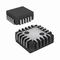
IC DRIVER DOT BAR DISPLAY 20PLCC
Manufacturer
National Semiconductor
Datasheet
1.LM3914VXNOPB.pdf
(22 pages)
Specifications of LM3914V/NOPB
Display Type
LED, LCD, Vacuum Fluorescent
Configuration
Dot/Bar Display
Digits Or Characters
10 Steps
Current - Supply
6.1mA
Voltage - Supply
3 V ~ 20 V
Operating Temperature
0°C ~ 70°C
Mounting Type
Surface Mount
Package / Case
20-PLCC
Led Driver Application
Bar-Graph Meter, Expanded Scale Meter
No. Of Outputs
10
Output Current
30mA
Output Voltage
1.34V
Input Voltage
3V To 15V
Dimming Control Type
Analog
Rohs Compliant
Yes
Lead Free Status / RoHS Status
Lead free / RoHS Compliant
Interface
-
Lead Free Status / Rohs Status
RoHS Compliant part
Other names
*LM3914V
LM3914V
LM3914V
Available stocks
Company
Part Number
Manufacturer
Quantity
Price
Company:

Part Number:
LM3914V/NOPB
Manufacturer:
TI
Quantity:
445
Company:
Part Number:
LM3914V/NOPB
Manufacturer:
Texas Instruments
Quantity:
10 000


Mode Pin Functional Description
DOT MODE CARRY
In order for the display to make sense when multiple
LM3914s are cascaded in dot mode, special circuitry has
been included to shut off LED No. 10 of the first device when
LED No. 1 of the second device comes on. The connection
for cascading in dot mode has already been described and is
depicted below.
As long as the input signal voltage is below the threshold of
the second LM3914, LED No. 11 is off. Pin 9 of LM3914
No. 1 thus sees effectively an open circuit so the chip is in
dot mode. As soon as the input voltage reaches the thresh-
old of LED No. 11, pin 9 of LM3914 No. 1 is pulled an LED
drop (1.5V or more) below V
comparator C2, referenced 600mV below V
the output of C2 low, which shuts off output transistor Q2,
extinguishing LED No. 10.
V
very small current (less than 100µA) that is diverted from
LED No. 9 does not noticeably affect its intensity.
An auxiliary current source at pin 1 keeps at least 100µA
flowing through LED No. 11 even if the input voltage rises
high enough to extinguish the LED. This ensures that pin 9 of
LM3914 No. 1 is held low enough to force LED No. 10 off
when any higher LED is illuminated. While 100µA does not
normally produce significant LED illumination, it may be
noticeable when using high-efficiency LEDs in a dark envi-
ronment. If this is bothersome, the simple cure is to shunt
LED No. 11 with a 10k resistor. The 1V IR drop is more than
the 900mV worst case required to hold off LED No. 10 yet
small enough that LED No. 11 does not conduct significantly.
(Continued)
LED
is sensed via the 20k resistor connected to pin 11. The
LED
. This condition is sensed by
LED
Cascading LM3914s in Dot Mode
. This forces
9
OTHER DEVICE CHARACTERISTICS
The LM3914 is relatively low-powered itself, and since any
number of LEDs can be powered from about 3V, it is a very
efficient display driver. Typical standby supply current (all
LEDs OFF) is 1.6mA (2.5mA max). However, any reference
loading adds 4 times that current drain to the V
supply input. For example, an LM3914 with a 1mA reference
pin load (1.3k), would supply almost 10mA to every LED
while drawing only 10mA from its V
the IC is typically drawing less than 10% of the current
supplied to the display.
The display driver does not have built-in hysteresis so that
the display does not jump instantly from one LED to the next.
Under rapidly changing signal conditions, this cuts down
high frequency noise and often an annoying flicker. An “over-
lap” is built in so that at no time between segments are all
LEDs completely OFF in the dot mode. Generally 1 LED
fades in while the other fades out over a mV or more of
range (Note 3). The change may be much more rapid be-
tween LED No. 10 of one device and LED No. 1 of a second
device “chained” to the first.
The LM3914 features individually current regulated LED
driver transistors. Further internal circuitry detects when any
driver transistor goes into saturation, and prevents other
circuitry from drawing excess current. This results in the
ability of the LM3914 to drive and regulate LEDs powered
from a pulsating DC power source, i.e., largely unfiltered.
(Due to possible oscillations at low voltages a nominal by-
pass capacitor consisting of a 2.2µF solid tantalum con-
nected from the pulsating LED supply to pin 2 of the LM3914
is recommended.) This ability to operate with low or fluctu-
ating voltages also allows the display driver to interface with
logic circuitry, opto-coupled solid-state relays, and low-
current incandescent lamps.
+
pin supply. At full-scale,
www.national.com
00797006
+
(pin 3)
Related parts for LM3914V/NOPB
Image
Part Number
Description
Manufacturer
Datasheet
Request
R

Part Number:
Description:
IC, DOT/BAR DISPLAY DRIVER, LCC-20
Manufacturer:
National Semiconductor
Datasheet:

Part Number:
Description:
Audio Power Driver (discontinued)
Manufacturer:
National Semiconductor Corporation
Datasheet:
Part Number:
Description:
National Semiconductor [8-Bit D/A Converter]
Manufacturer:
National Semiconductor
Datasheet:
Part Number:
Description:
National Semiconductor [Media Coprocessor]
Manufacturer:
National Semiconductor
Datasheet:
Part Number:
Description:
Digitally Controlled Tone and Volume Circuit with Stereo Audio Power Amplifier, Microphone Preamp Stage and National 3D Sound
Manufacturer:
National Semiconductor
Datasheet:
Part Number:
Description:
Digitally Controlled Tone and Volume Circuit with Stereo Audio Power Amplifier, Microphone Preamp Stage and National 3D Sound
Manufacturer:
National Semiconductor
Datasheet:
Part Number:
Description:
AC97 Rev 2 Codec with Sample Rate Conversion and National 3D Sound
Manufacturer:
National Semiconductor
Part Number:
Description:
Manufacturer:
National Semiconductor
Datasheet:
Part Number:
Description:
Manufacturer:
National Semiconductor
Datasheet:
Part Number:
Description:
General Purpose, Low Voltage, Low Power, Rail-to-Rail Output Operational Amplifiers
Manufacturer:
National Semiconductor
Datasheet:
Part Number:
Description:
8-bit 20 MSPS flash A/D converter.
Manufacturer:
National Semiconductor
Datasheet:
Part Number:
Description:
Low Noise Quad Operational Amplifier
Manufacturer:
National Semiconductor
Datasheet:
Part Number:
Description:
Quad Differential Line Receivers
Manufacturer:
National Semiconductor
Datasheet:
Part Number:
Description:
Quad High Speed Trapezoidal? Bus Transceiver
Manufacturer:
National Semiconductor
Datasheet: