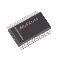
MAX6955AAX+T Maxim Integrated Products, MAX6955AAX+T Datasheet - Page 20

MAX6955AAX+T
Manufacturer Part Number
MAX6955AAX+T
Description
IC DRVR DSPL LED 36-SSOP
Manufacturer
Maxim Integrated Products
Datasheet
1.MAX6955AAX.pdf
(43 pages)
Specifications of MAX6955AAX+T
Display Type
LED
Configuration
7, 14, 16 Segment
Interface
I²C
Current - Supply
22mA
Voltage - Supply
2.7 V ~ 5.5 V
Operating Temperature
-40°C ~ 125°C
Mounting Type
Surface Mount
Package / Case
36-SSOP
Number Of Digits
16
Number Of Segments
128
Low Level Output Current
935 mA
High Level Output Current
55 mA
Operating Supply Voltage
2.7 V to 5.5 V
Maximum Supply Current
30 mA
Maximum Power Dissipation
941 mW
Maximum Operating Temperature
+ 125 C
Mounting Style
SMD/SMT
Minimum Operating Temperature
- 40 C
Lead Free Status / RoHS Status
Lead free / RoHS Compliant
Digits Or Characters
-
Lead Free Status / Rohs Status
Details
2-Wire Interfaced, 2.7V to 5.5V LED Display
Driver with I/O Expander and Key Scan
The MAX6955 drives a peak current of 40mA into LEDs
with a 2.2V forward-voltage drop when operated from a
supply voltage of at least 3.0V. The minimum voltage
drop across the internal LED drivers is therefore (3.0V -
2.2V) = 0.8V. If a higher supply voltage is used, the dri-
ver absorbs a higher voltage, and the driver’s power
dissipation increases accordingly. However, if the LEDs
used have a higher forward-voltage drop than 2.2V, the
supply voltage must be raised accordingly to ensure
that the driver always has at least 0.6V of headroom.
The voltage drop across the drivers with a nominal 5V
supply (5.0V - 2.2V) = 2.8V is nearly 3 times the drop
across the drivers with a nominal 3.3V supply (3.3V -
2.2V) = 1.1V. In most systems, consumption is an
important design criterion, and the MAX6955 should be
operated from the system’s 3.3V nominal supply. In
other designs, the lowest supply voltage may be 5V.
The issue now is to ensure the dissipation limit for the
MAX6955 is not exceeded. This can be achieved by
inserting a series resistor in the supply to the MAX6955,
ensuring that the supply decoupling capacitors are still
on the MAX6955 side of the resistor. For example, con-
sider the requirement that the minimum supply voltage
to a MAX6955 must be 3.0V, and the input supply
range is 5V ±5%. Maximum supply current is 35mA +
(40mA x 17) = 715mA. Minimum input supply voltage is
4.75V. Maximum series resistor value is (4.75V -
3.0V)/0.715A = 2.44Ω. We choose 2.2Ω ±5%. Worst-
case resistor dissipation is at maximum toleranced
resistance, i.e., (0.715A) 2 x (2.2Ω x 1.05) = 1.18W. The
maximum MAX6955 supply voltage is at maximum
input supply voltage and minimum toleranced resis-
tance, i.e., 5.25V - (0.715A x 2.2Ω x 0.95) = 3.76V.
The MAX6955 works over the 2.7V to 5.5V supply
range. The minimum useful supply voltage is deter-
mined by the forward-voltage drop of the LEDs at the
peak current I
the driver output stages. The MAX6955 correctly regu-
lates I
voltage. If the supply drops below this minimum volt-
20
______________________________________________________________________________________
SEG
Choosing Supply Voltage to Minimize
with a supply voltage above this minimum
SEG
, plus the 0.8V headroom required by
Low-Voltage Operation
Power Dissipation
age, the driver output stages can brown out, and be
unable to regulate the current correctly. As the supply
voltage drops further, the LED segment drive current
becomes effectively limited by the output driver's on-
resistance, and the LED drive current drops. The char-
acteristics of each individual LED in a display digit are
well matched, so the result is that the display intensity
dims uniformly as supply voltage drops out of regula-
tion and beyond.
The upper limit for power dissipation (P
MAX6955 is determined from the following equation:
where:
V+ = supply voltage
DUTY = duty cycle set by intensity register
N = number of segments driven (worst case is 17)
V
I
P
Dissipation example:
Thus, for a 36-pin SSOP package (T
So T
at a maximum package temperature of +85°C.
The MAX6955 operates from a single 2.7V to 5.5V
power supply. Bypass the power supply to GND with a
0.1µF capacitor as close to the device as possible. Add
a 47µF capacitor if the MAX6955 is not close to the
board’s input bulk decoupling capacitor.
+85°C/W from Operating Ratings), the maximum
allowed ambient temperature T
SEG
LED
D
P
= Power dissipation, in mW if currents are in mA
D
T
A
= segment current set by R
= LED forward voltage at I
J(MAX)
= (V+ x 35mA) + (V+ - V
= +90.5°C. Thus, the part can be operated safely
V
I
SEG
LED
P
D
= 3.6V (35mA) + (3.6V - 2.4V)(15/16 x
= T
= T
= 30mA, N = 17, DUTY = 15/16,
= 2.4V at 30mA, V+ = 3.6V
30mA x 17) = 0.700W
A
A
Computing Power Dissipation
+ (P
+ (0.700 x +85°C/W)
D
x T
JA
) = +150°C
LED
A
SEG
SET
is given by:
) (DUTY x I
Power Supplies
JA
= 1/0.0118 =
SEG
D
) for the
x N)


