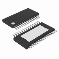
MAX7456EUI+T Maxim Integrated Products, MAX7456EUI+T Datasheet - Page 11

MAX7456EUI+T
Manufacturer Part Number
MAX7456EUI+T
Description
IC DISPLAY 1CH W/EEPROM 28TSSOP
Manufacturer
Maxim Integrated Products
Type
OSD (On-Screen Display) Video Generatorr
Datasheet
1.MAX7456EUI.pdf
(44 pages)
Specifications of MAX7456EUI+T
Applications
Security Systems, Video Routing
Mounting Type
Surface Mount
Package / Case
28-TSSOP Exposed Pad, 28-eTSSOP, 28-HTSSOP
Current - Supply
58mA
Voltage - Supply
4.75 V ~ 5.25 V
Operating Temperature
-40°C ~ 85°C
Interface
SPI Serial
Display Type
OSD
Digits Or Characters
256 Characters
Lead Free Status / RoHS Status
Lead free / RoHS Compliant
Configuration
-
Lead Free Status / Rohs Status
Details
The MAX7456’s clamp is a DC-restore circuit that uses
the input coupling capacitor to correct any DC shift of
the input signal, on a line-by-line basis, such that the
sync tip at VIN is approximately 550mV. This establish-
es a DC level at VIN suitable for the on-chip sync
detection and video processing functions. This circuitry
also removes low-frequency noise such as 60Hz hum
or other additive low-frequency noise.
Figure 3. Definition of Terms
Table 1. Video Sync Modes
X = Don’t care.
Auto Sync Select Mode
External Sync Select
Internal Sync Select
VIN
VM0[5, 4] = 10
VM0[5, 4] = 11
VM0[5, 4] = 0x
VIDEO MODE
______________________________________________________________________________________
SYNC TIP
LEVEL
Single-Channel Monochrome On-Screen
COLOR BURST
No input
No input
No input
Video
Video
Video
VIN
MINIMUM VIDEO SWING
Display with Integrated EEPROM
Input Clamp
Inactive (high)
VSYNC
Active
Active
Active
Active
Active
WHITE LEVEL
MAXIMUM VIDEO SWING
The sync separator detects the composite sync pulses
on the video input and extracts the timing information to
generate HSYNC and VSYNC. It is also used for inter-
nal OSD synchronization and loss-of-sync (LOS) detec-
tion. LOS goes high if no sync signal is detected at VIN
for 32 consecutive lines, and goes low if 32 consecu-
tive horizontal sync signals are detected. During a LOS
condition, when VM0[5] = 0 (Video Mode 0 register, bit
5), only the OSD appears at the VOUT. At this time, the
input image is set to a gray level at VOUT as deter-
mined by VM1[6:4]. The behavior of all sync modes is
shown in Table 1.
BLACK LEVEL
Inactive (high)
HSYNC
Active
Active
Active
Active
Active
High
High
High
High
LOS
Low
Low
Sync Separator
INPUT VOLTAGE
V
V
OSD only
OSD only
OSD only
IN
IN
VOUT
DC
+ OSD
+ OSD
11


