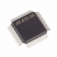
MAX6960AMH+D Maxim Integrated Products, MAX6960AMH+D Datasheet - Page 28

MAX6960AMH+D
Manufacturer Part Number
MAX6960AMH+D
Description
IC DRVR LED 8X8 44-MQFP
Manufacturer
Maxim Integrated Products
Datasheet
1.MAX6963ATH.pdf
(35 pages)
Specifications of MAX6960AMH+D
Display Type
LED
Configuration
8 x 8 (Matrix)
Interface
4-Wire Serial
Digits Or Characters
Any Digit Type
Current - Supply
7.5mA
Voltage - Supply
2.7 V ~ 3.6 V
Operating Temperature
-40°C ~ 125°C
Mounting Type
Surface Mount
Package / Case
44-MQFP, 44-PQFP
Number Of Segments
64
Low Level Output Current
750000 uA
High Level Output Current
48000 uA
Operating Supply Voltage
2.7 V to 3.6 V
Maximum Supply Current
11 mA
Maximum Power Dissipation
1012 mW
Maximum Operating Temperature
+ 125 C
Mounting Style
SMD/SMT
Minimum Operating Temperature
- 40 C
Lead Free Status / RoHS Status
Lead free / RoHS Compliant
4-Wire Serially Interfaced
8 x 8 Matrix Graphic LED Drivers
Figure 13. RISET0 and RISET1 Internal Architecture
Figure 14. RISET0 and RISET1 Pin Connections
28
______________________________________________________________________________________
RISET0
RISET1
42
43
R
R
INT
INT
V
V
42
43
REF
REF
SETTING LED CURRENT
RISET0
RISET1
MAX6960–
MAX6963
TO 40mA
MAX6960
MAX6961
MAX6962
MAX6963
NO CONNECTION
NO CONNECTION
LED DRIVERS
LED DRIVERS
TO GREEN
TO RED
R
R
INT
INT
42
43
SETTING LED CURRENT
RISET0
RISET1
MAX6960–
MAX6963
TO 20mA
The MAX6960 contains an overtemperature (OT) detec-
tion circuit, which trips at a die temperature of typically
+150°C. The OT event is latched, and is readable in the
fault and device ID register (Table 32). When the OT
trips, the MAX6960 shutdown bit in the configuration
register (Table 15) is cleared, and the driver goes into
shutdown. Data is not lost; the effect is the same as the
user setting the shutdown bit. The user can attempt to
set the shutdown bit at any time. However, if the driver
is still over temperature, then the attempt to set the
shutdown bit is ignored. The OT fault flag is NOT auto-
matically cleared when the device cools, or when the
device is taken out of shutdown.
The fault and device ID register is cleared on power-
up, and can also be cleared by writing to it. The fault
flags are NOT cleared by a read. When writing the fault
and device ID register, the data written is ignored; all
fault flags are cleared, including the LED flags. It is
possible to clear all MAX6960s on a bus by performing
a global write to the fault and device ID register.
The MAX6960 can be configured for pretrimmed 20mA
or 40mA LED current, or a 20mA to 40mA adjustable
current, on a digit-by-digit basis by the RISET0 and
RISET1 pin connections (Figures 13 and 14). The digit
intensity registers can be used to digitally adjust the
segment current, again on a digit-by-digit basis, by
controlling the PWM. Some applications best use one
or the other technique; some applications may require
the flexibility of both.
R0
Overtemperature Fault Detection
Applications Information
R1
42
43
ADJUSTABLE LED CURRENT
RISET0
RISET1
Setting LED Drive Current
MAX6960–
MAX6963
20mA


