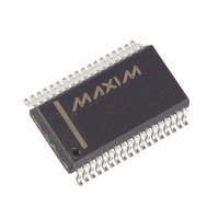
MAX5965BEAX+ Maxim Integrated Products, MAX5965BEAX+ Datasheet - Page 20

MAX5965BEAX+
Manufacturer Part Number
MAX5965BEAX+
Description
IC PSE CTRLR FOR POE 36SSOP
Manufacturer
Maxim Integrated Products
Type
Power Over Ethernet Controller (PoE)r
Datasheet
1.MAX5965AUAXT.pdf
(53 pages)
Specifications of MAX5965BEAX+
Applications
IP Phones, Power over LAN, Network Routers and Switches
Internal Switch(s)
No
Voltage - Supply
2.4 V ~ 3.6 V
Operating Temperature
-40°C ~ 85°C
Mounting Type
Surface Mount
Package / Case
36-BSOP (0.300", 7.5mm Width)
Product
PoE / LAN Solutions
Supply Voltage (max)
60 V
Supply Voltage (min)
32 V
Power Dissipation
1388.9 mW
Operating Temperature Range
- 40 C to + 85 C
Mounting Style
SMD/SMT
Input Voltage
60V
Supply Current
4.8mA
Digital Ic Case Style
SSOP
No. Of Pins
36
Uvlo
28.5V
Frequency
400kHz
Filter Terminals
SMD
Interface
I2C
Rohs Compliant
Yes
Controller Type
Power Supply
Lead Free Status / RoHS Status
Lead free / RoHS Compliant
High-Power, Quad, Monolithic, PSE Controllers
for Power over Ethernet
A sense resistor R
V
conditions, the voltage across R
the threshold V
internal current-limiting circuit regulates the GATE_ volt-
age, limiting the current to I
transient conditions, if V
than 1V, a fast pulldown circuit activates to quickly
recover from the current overshoot. During startup, if
the current-limit condition persists, when the startup
timer, t
STRT_FLT_ bit is set. In the normal powered state, the
MAX5965A/MAX5965B check for overcurrent condi-
tions as determined by V
The t
ous overcurrent period. The t
when V
pace when V
ment for the t
ed short-duration overcurrents. When the counter
reaches the t
power off the port and assert the IMAX_FLT_ bit. For a
continuous overstress, a fault latches exactly after a
period of t
ICUT registers R2Ah[6:4], R2Ah[2:0], R2Bh[6:4],
R2Bh[2:0], and the IVEE bits in register R29h[1:0]. See
the High-Power Mode section for more information on
the ICUT register.
Figure 2. PGOOD_ Timing
20
EE
PGOOD_
monitors the load current. Under normal operating
______________________________________________________________________________________
POK_
FAULT
RS
START
FAULT
exceeds V
counter sets the maximum allowed continu-
RS
FAULT
, times out, the port shuts off, and the
FAULT
. V
drops below V
SU_LIM
SU_LIM
S
t
counter allows for detecting repeat-
PGOOD
FLT_LIM
connected between SENSE_ and
limit, the MAX5965A/MAX5965B
. If V
RS
Overcurrent Protection
FLT_LIM
is programmable through the
exceeds V
LIM
and decreases at a slower
RS
FAULT
FLT_LIM
S
exceeds V
= V
(V
= ~88% of V
RS
SU_LIM
counter increases
. A slower decre-
) never exceeds
SU_LIM
/R
SU_LIM
S
by more
. During
SU_LIM
, an
.
After power-off due to an overcurrent fault, and if the
RSTR_EN bit is set, the t
reset but starts decrementing at the same slower pace.
The MAX5965A/MAX5965B allow the port to be pow-
ered on only when the t
feature sets an automatic duty-cycle protection to the
external MOSFET avoiding overheating.
The MAX5965A/MAX5965B continuously flag when the
current exceeds the maximum current allowed for the
class as indicated in the CLASS status register. When
class overcurrent occurs, the MAX5965A/MAX5965B
set the IVC_ bit in register R09h.
The ICUT register determines the maximum current lim-
its allowed for each port of the MAX5965A/MAX5965B.
The 3 ICUT bits (R2Ah[6:4], R2Ah[2:0], R2Bh[6:4], and
R2Bh[2:0]) allow programming of the current-limit and
overcurrent thresholds in excess of the IEEE standard
limit (see Tables 34a, 34b, and 34c). The ICUT regis-
ters can be written to directly through the I
when CL_DISC (R17h[2]) is set to 0 (see Table 3). In
this case, the current limit of the port is configured
regardless of the status of the classification.
By setting the CL_DISC bit to 1, the MAX5965A/
MAX5965B automatically set the ICUT register based
upon the classification result of the port. See Table 3
and the Register Map and Description section.
When CL_DISC (R17h[2]) is set to 0, high-power mode
is configured by setting the ICUT bits to any combina-
tion other than 000, 110, or 111 (note that 000 is the
default value for the IEEE standard limit). See Table 3
and the Register Map and Description section.
During startup and normal operation, an internal circuit
senses the voltage at OUT_ and reduces the current-
limit value when (V
function helps to reduce the power dissipation on the
FET. The current limit eventually reduces down to 1/3 of
I
high-power mode, the foldback starts when (V
V
current limit (I
back current (V
LIM
EE
) > 10V (see Figure 3b). In high-power mode, the
when (V
ICUT Register and High-Power Mode
OUT
LIM
TH_FB
_ - V
) is reduced down to minimum fold-
OUT
/R
EE
S
_ - V
) when (V
FAULT
FAULT
) > 48V (see Figure 3a). For
EE
timer is not immediately
counter is at zero. This
) > 28V. The foldback
Foldback Current
OUT
High-Power Mode
_ - V
ICUT Register
EE
2
C interface
) > 48V.
OUT
_ -


