LP3958TL/NOPB National Semiconductor, LP3958TL/NOPB Datasheet
LP3958TL/NOPB
Specifications of LP3958TL/NOPB


Related parts for LP3958TL/NOPB


LP3958TL/NOPB Summary of contents
Page 1
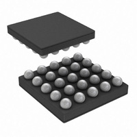
... The device is controlled through 2-wire low voltage I compatible interface that reduces the number of required connections. LP3958 is offered in a tiny 25-bump micro-SMD package. Typical Application © 2006 National Semiconductor Corporation Features n High efficiency boost converter with programmable output voltage n 2 individual drivers for serial display backlight LEDs ...
Page 2
Connection Diagrams and Package Mark Information CONNECTION DIAGRAMS Top View PACKAGE MARK ORDERING INFORMATION Order Number LP3958TL LP3958TLX www.national.com 25-Bump Thin Micro SMD Package, Large Bump NS Package Number TLA25CCA 20175571 Package Marking Supplied As SJHB TNR 250 SJHB TNR ...
Page 3
Connection Diagrams and Package Mark Information PIN DESCRIPTIONS Pin # Name Type 5E SW Output 5D FB Input 5C KEY1 Output 5B KEY2 Output 5A KEY3 Output 4E GND_SW Ground 4D NRST Input 4C SCL Logic Input 4B IKEY Input ...
Page 4
... Absolute Maximum Ratings 2) If Military/Aerospace specified devices are required, please contact the National Semiconductor Sales Office/ Distributors for availability and specifications. V (SW, FB, MAIN, SUB, KEY1, KEY2, KEY3 DD1 DD2 DDIO DDA Voltage KEY RT REF Voltage on Logic Pins REF I(KEY1, KEY2, KEY3) ...
Page 5
... C (typ.). J Note 4: For detailed soldering specifications and information, please refer to National Semiconductor Application Note AN1112 : Micro SMD Wafer Level Chip Scale Package Note 5: The Human body model is a 100pF capacitor discharged through a 1.5kΩ resistor into each pin. The machine model is a 200pF capacitor discharged directly into each pin ...
Page 6
Block Diagram www.national.com 6 20175574 ...
Page 7
Modes of Operation RESET: In the RESET mode all the internal registers are reset to the default values. Reset is entered always if input NRST is LOW or internal Power On Reset is active. Power On Reset (POR) will activate ...
Page 8
Power-Up Sequence When powering up the device, V DD1 greater than V to prevent any damage to the device. DDIO Magnetic Boost DC/DC Converter The LP3958 Boost DC/DC Converter generates an 8…18V supply voltage for the LEDs from single Li-Ion ...
Page 9
Magnetic Boost DC/DC Converter MAGNETIC BOOST DC/DC CONVERTER ELECTRICAL CHARACTERISTICS Symbol Parameter I Maximum Continuous Load LOAD Current V Output Voltage Accuracy OUT (FB Pin) RDS Switch ON Resistance ON f PWM Mode Switching PWM Frequency Frequency Accuracy t Switch ...
Page 10
Boost Converter Typical Performance Characteristics Vin = 3.6V, Vout = 18.0V if not otherwise stated Boost Converter Efficiency Battery Current vs Voltage Boost Line Regulation 3.0V - 3.6V, no load www.national.com Boost Typical Waveforms at 70mA Load 20175579 Boost Output ...
Page 11
Boost Converter Typical Performance Characteristics Boost Load Transient Response 25mA – 70mA Boost Maximum Current vs. Output Voltage Autoload Effect on Input Current, No Load 20175585 20175595 11 (Continued) 20175586 www.national.com ...
Page 12
Functionality of Keypad LED Outputs (KEY1, KEY2, KEY3) LP3958 has three individual keypad LED output pins. Output pins can be used in switch mode or constant current mode. Output mode can be selected with the control register (ad- dress 00H) ...
Page 13
Functionality of Keypad LED Outputs (KEY1, KEY2, KEY3) The non-overlapping mode has 8-programmed balance ra- tios. Since the KEY1, KEY2 and KEY3 are split in to non- overlapping slots the output current through the keypad LED can be calculated by ...
Page 14
Functionality of Keypad LED Outputs (KEY1, KEY2, KEY3) External PWM Control The GPIO[0]/PWM pin can be used to control the KEY output. PWM function for the pin is selected by writing EN- _PWM_PIN high in GPIO control register (address 06H). ...
Page 15
Backlight Drivers LP3958 has 2 independent backlight drivers. Both drivers are regulated constant current sinks. LED current for both LED strings are controlled by the 8-bit current mode DACs with 0.1 mA step. MAIN and SUB LEDs can be also ...
Page 16
Backlight Drivers (Continued) FADE IN / FADE OUT LP3958 has an automatic fade in and out for main and sub backlight. The fade function is enabled with EN_FADE bit. The slope of the fade curve is set by the SLOPE ...
Page 17
Backlight Driver Electrical Characteristics Symbol Parameter I Maximum Sink Current MAX I Leakage Current LEAKAGE I MAIN Current tolerance MAIN I SUB Current tolerance SUB Match Sink Current Matching Error MAIN-SUB Match Sink Current Matching Error MAIN-SUB V 95% Saturation ...
Page 18
General Purpose I/O Functionality LP3958 has three general purpose I/O pins: GPIO[0]/PWM, GPIO[1] and GPIO[2]. GPIO[0]/PWM can also be used as a PWM input for the external LED PWM controlling. GPIO bi-directional drivers are operating from the V domain. Registers ...
Page 19
I C Compatible Interface SIGNALS 2 The SCL pin is used for the I C clock and the SDA pin is used for bidirectional data transfer. Both these signals need 2 a pull-up resistor according to ...
Page 20
I C Compatible Interface w = write (SDA = “0” read (SDA = “1”) ack = acknowledge (SDA pulled down by either master or slave repeated start id = 7-bit chip address, 59H (101 1001b) ...
Page 21
I C Compatible Interface TIMING PARAMETERS (V = 3.0 to 4.5V, V DD1,2 Symbol 1 Hold Time (repeated) START Condition 2 Clock Low Time 3 Clock High Time 4 Setup Time for a Repeated START Condition ...
Page 22
Recommended External Components OUTPUT CAPACITOR, C OUT The output capacitor C directly affects the magnitude of OUT the output ripple voltage. In general, the higher the value the lower the output ripple magnitude. Multilayer ce- OUT ramic ...
Page 23
23 www.national.com ...
Page 24
LP3958 Register Bit Explanations Each register is shown with a key indicating the accessibility of the each individual bit, and the initial condition: CONTROL REGISTER (00H) – KEYPAD LEDS CONTROL REGISTER D7 D6 KEYP_PWM EN_KEYP ...
Page 25
LP3958 Register Bit Explanations KEYPAD MAX CURRENT (02H) – MAXIMUM KEYPAD CURRENT CONTROL REGISTER WLED CONTROL (03H) – WLED CONTROL REGISTER SLOPE ...
Page 26
LP3958 Register Bit Explanations MAIN CURRENT (04H) – MAIN CURRENT CONTROL REGISTER SUB CURRENT (05H) – SUB CURRENT CONTROL REGISTER GPIO CONTROL (06H) – ...
Page 27
LP3958 Register Bit Explanations ENABLES (0BH) – ENABLES REGISTER NSTBY EN_BOOST NSTBY EN_BOOST EN_AUTOLOAD BOOST OUTPUT (0DH) – BOOST OUTPUT VOLTAGE CONTROL REGISTER ...
Page 28
... BANNED SUBSTANCE COMPLIANCE National Semiconductor manufactures products and uses packing materials that meet the provisions of the Customer Products Stewardship Specification (CSP-9-111C2) and the Banned Substances and Materials of Interest Specification (CSP-9-111S2) and contain no ‘‘Banned Substances’’ as defined in CSP-9-111S2. ...