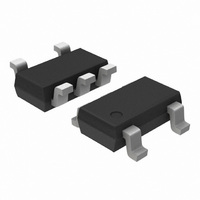
CAT4201TD-GT3 ON Semiconductor, CAT4201TD-GT3 Datasheet - Page 8

CAT4201TD-GT3
Manufacturer Part Number
CAT4201TD-GT3
Description
IC LED DRIVER HIGH BRIGHT TSOT-5
Manufacturer
ON Semiconductor
Type
HBLED Driverr
Specifications of CAT4201TD-GT3
Topology
PWM, Step-Down (Buck)
Number Of Outputs
1
Internal Driver
Yes
Type - Primary
Automotive, Backlight
Type - Secondary
High Brightness LED (HBLED)
Frequency
1MHz
Voltage - Supply
6.5 V ~ 36 V
Voltage - Output
36V
Mounting Type
Surface Mount
Package / Case
TSOT-23-5, TSOT-5, TSOP-5
Operating Temperature
-40°C ~ 125°C
Current - Output / Channel
350mA
Internal Switch(s)
Yes
Efficiency
94%
Number Of Segments
1
Operating Supply Voltage
6.5 V to 28 V
Maximum Supply Current
0.4 mA
Maximum Operating Temperature
+ 125 C
Mounting Style
SMD/SMT
Minimum Operating Temperature
- 40 C
Lead Free Status / RoHS Status
Lead free / RoHS Compliant
Other names
CAT4201TD-GT3TR
Available stocks
Company
Part Number
Manufacturer
Quantity
Price
Simplified Block Diagram
Basic Operation
designed to drive series connected high−power LEDs. LED
strings with total forward voltages of up to 32 V can be
driven with bias currents of up to 350 mA.
voltage power MOSFET allows the inductor current to
charge linearly until the peak maximum level is reached, at
which point the MOSFET is switched off and the second
phase commences, allowing the inductor current to then
flow through the Schottky diode circuit and discharge
linearly back to zero current.
operate at the cross−over point between Continuous
Conduction Mode (CCM) and Discontinuous Conduction
Mode (DCM). This operating mode results in an average
LED current which is equal to half of the peak switching
current.
The CAT4201 is a high efficiency step−down regulator
During the first switching phase, an integrated high
The switching architecture ensures the device will always
CTRL
12 V/24 V
20 mA
Reference
1.2 V
30 kW
+
–
Figure 22. CAT4201 Simplified Block Diagram
EN
7 V
RSET
1.2 V
http://onsemi.com
EN
8
Controller
VBAT
PWM
LED Pin Current
connected to the regulated output of the RSET pin. An
overall current gain ratio of approximately 2.5 A/mA exists
between the average LED current and the RSET current,
hence the following equation can be used to calculate the
LED current.
RSET resistors.
Table 6. RSET RESISTOR SELECTION
The LED current is set by the external RSET resistor
Table 6 lists the various LED currents and the associated
OFF−Time Control
ON−Time Control
LED Current (A)
LED Current (A) ^ 2.5
0.10
0.15
0.20
0.25
0.30
0.35
1 W
R
2
GND
SW
R
V
RSET
SET
RSET (kW)
8.25
(kW)
33
21
15
12
10
(V)


