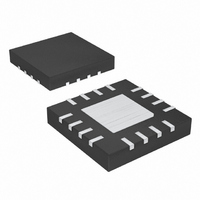
MAX16803ATE+ Maxim Integrated Products, MAX16803ATE+ Datasheet - Page 3

MAX16803ATE+
Manufacturer Part Number
MAX16803ATE+
Description
IC LED DRIVR HIGH BRIGHT 16-TQFN
Manufacturer
Maxim Integrated Products
Type
HBLED Driverr
Datasheet
1.MAX16803ATET.pdf
(11 pages)
Specifications of MAX16803ATE+
Topology
PWM
Number Of Outputs
1
Internal Driver
Yes
Type - Primary
Automotive
Type - Secondary
High Brightness LED (HBLED)
Voltage - Supply
6.5 V ~ 40 V
Voltage - Output
5.27V
Mounting Type
Surface Mount
Package / Case
16-TQFN Exposed Pad
Operating Temperature
-40°C ~ 125°C
Current - Output / Channel
350mA
Internal Switch(s)
Yes
Low Level Output Current
35 mA
High Level Output Current
350 mA
Operating Supply Voltage
6.5 V to 40 V
Maximum Supply Current
1.4 mA
Maximum Power Dissipation
2666.7 mW
Maximum Operating Temperature
+ 125 C
Mounting Style
SMD/SMT
Minimum Operating Temperature
- 40 C
For Use With
MAX16803EVKIT+ - EVAL KIT FOR MAX16803
Lead Free Status / RoHS Status
Lead free / RoHS Compliant
Frequency
-
Efficiency
-
Lead Free Status / Rohs Status
Lead free / RoHS Compliant
ELECTRICAL CHARACTERISTICS (continued)
(V
T
Note 1: All devices 100% production tested at T
Note 2: Resistors were added from OUT to CS+ to aid with the power dissipation during testing.
Note 3: Dropout is measured as follows:
Note 4: I
Note 5: t
Note 6: Current regulation varies with V5 load (see the Typical Operating Characteristics ).
Note 7: Thermal shutdown does not function if the output of the 5V reference is shorted to ground.
(V
THERMAL OVERLOAD
Thermal-Shutdown Temperature
Thermal-Shutdown Hysteresis
+5V REGULATOR
Output Voltage Regulation
V5 Short-Circuit Current
J
IN
IN
= -40°C to +125°C, unless otherwise noted. Typical values are at T
450
400
350
300
250
200
150
100
50
= V
= V
0
-40
EN
EN
Connect R
Reduce V
for I
-25
V5
ON
PARAMETER
Driver with PWM Dimming and 5V Regulator
= +12V, C
= +12V, T
-10 5 20 35 50
= 0mA.
OUT
time includes the delay and the rise time needed for I
High-Voltage, 350mA, High-Brightness LED
I
OUTPUT CURRENT
vs. TEMPERATURE
LOAD
I
I
LOAD
LOAD
TEMPERATURE (°C)
to drop below 10%. See the Typical Operating Characteristics . t
IN
= 35mA
I
O
LOAD
= 100mA
= 350mA
_______________________________________________________________________________________
A
until V
V5
= 27Ω from OUT to CS+. Connect R
= +25°C, unless otherwise noted.)
= 200mA
= 0.1µF to GND, I
65 80
OUT
= 0.97 x V
95
110
SYMBOL
125
V5
OUT1
V5
= 0, V
0.210
0.209
0.208
0.207
0.206
0.205
0.204
0.203
0.202
0.201
0.200
(record as V
A
(Note 6)
V5 = 0V (Note 7)
= +25°C. Limits over the operating temperature range are guaranteed by design.
20
CS-
V
(V
IN
50
= 0V, V
CS+
= 12V
80 110 140 170 200
SENSE
- V
IN2
OUTPUT CURRENT (mA)
CS-
DIM
) vs. OUTPUT CURRENT
and V
= 0.58Ω from CS+ to CS-. Set V
CONDITIONS
OUT
= +4V, connect R
A
OUT2
Typical Operating Characteristics
= +25°C.) (Note 1)
to reach 90% of its final value. t
230 260
). ∆V
290
DO
320
ON
= V
350
and t
SENSE
IN2
OFF
- V
= 0.58Ω between CS+ and CS- (Note 1).
OUT2
are tested with 13Ω from OUT to CST.
400
350
300
250
200
150
100
50
0
IN
MIN
5.0
.
0
= +12V (record V
OFF
5
10
+155
time is the time needed
vs. INPUT VOLTAGE
TYP
5.27
OUTPUT CURRENT
23
16
INPUT VOLTAGE (V)
15
20
MAX
OUT
5.5
25
as V
30
UNITS
OUT1
mA
35
°C
°C
V
).
40
3


