MAX16834AUP+ Maxim Integrated Products, MAX16834AUP+ Datasheet - Page 13

MAX16834AUP+
Manufacturer Part Number
MAX16834AUP+
Description
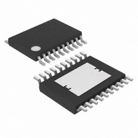
IC LED DRVR HIGH BRIGHT 20-TSSOP
Manufacturer
Maxim Integrated Products
Type
HBLED Driverr
Datasheet
1.MAX16834ATP.pdf
(23 pages)
Specifications of MAX16834AUP+
Topology
PWM, SEPIC, Step-Down (Buck), Step-Up (Boost)
Number Of Outputs
1
Internal Driver
No
Type - Primary
Automotive, Backlight
Type - Secondary
High Brightness LED (HBLED), RGB
Frequency
100kHz ~ 1MHz
Voltage - Supply
4.75 V ~ 28 V
Mounting Type
Surface Mount
Package / Case
20-TSSOP Exposed Pad, 20-eTSSOP, 20-HTSSOP
Operating Temperature
-40°C ~ 125°C
Internal Switch(s)
Yes
Lead Free Status / RoHS Status
Lead free / RoHS Compliant
Voltage - Output
-
Current - Output / Channel
-
Efficiency
-
Lead Free Status / Rohs Status
Details
Figure 3. Boost-Buck LED Driver (V
ESR and the bulk capacitance are equal, allowing 50%
of the ripple for the bulk capacitance. The capacitance
is given by:
where I
hertz, and ΔV
of allowable ripple is for the ESR of the output capaci-
tor. Based on this, the ESR of the output capacitor is
given by:
where IL
High-Power LED Driver with Integrated High-Side LED
Current Sense and PWM Dimming MOSFET Driver
V
IN
LED
P
is the peak inductor current in amperes.
R1
R2
is in amperes, C
C
ESR
OUTRIPPLE
OUT
COUT
C1
______________________________________________________________________________________
≥
Δ
V
I
LED
<
OUTRIPPLE
is in volts. The remaining 50%
Δ
V
× ×
R3
C4
R5
C2
C5
OUTRIPPLE
OUT
2
(
IL
LED+
P
D
is in farads, f
×
MAX
×
R6
< 28V)
) 2
f
SW
( )
IN
UVEN
SC
RT/SYNC
V
REFI
FLT
SGND
LV
REF
Ω
CC
MAX16834
SW
is in
PWMDIM
DIMOUT
SENSE+
COMP
NDRV
PGND
OVP+
CLV
CS
HV
Use the below equation to calculate the RMS current
rating of the output capacitor:
The input filter capacitor bypasses the ripple current
drawn by the converter and reduces the amplitude of
high-frequency current conducted to the input supply.
The ESR, ESL, and the bulk capacitance of the input
capacitor contribute to the input ripple. Use a low-ESR
input capacitor that can handle the maximum input
RMS ripple current from the converter.
For the boost configuration, the input current is the
same as the inductor current. For boost-buck
I
COUT(RMS)
ON
R7
C7
OFF
Q1
C6
=
L1
R8
D1
(IL
+
(
C3
IL
AVG
A
V V G
×
×
(1 D
D
-
R4
R9
Q2
MAX
MAX
Input Capacitor
)
2
))
×
R10
2
(
1 -
LED+
×
LED-
D
D
LEDs
MAX
C8
MAX
V
IN
)
13


