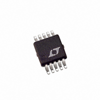
LT3003EMSE#PBF Linear Technology, LT3003EMSE#PBF Datasheet - Page 8

LT3003EMSE#PBF
Manufacturer Part Number
LT3003EMSE#PBF
Description
IC LED DRIVER BALLASTER 10-MSOP
Manufacturer
Linear Technology
Type
LED Ballasterr
Datasheet
1.LT3003EMSEPBF.pdf
(16 pages)
Specifications of LT3003EMSE#PBF
Topology
PWM, Step-Down (Buck), Step-Up (Boost)
Number Of Outputs
3
Internal Driver
Yes
Type - Primary
Automotive, Backlight
Voltage - Supply
3 V ~ 40 V
Mounting Type
Surface Mount
Package / Case
10-MSOP Exposed Pad, 10-HMSOP, 10-eMSOP
Operating Temperature
-40°C ~ 125°C
Current - Output / Channel
350mA
Internal Switch(s)
Yes
Lead Free Status / RoHS Status
Lead free / RoHS Compliant
Voltage - Output
-
Frequency
-
Efficiency
-
Available stocks
Company
Part Number
Manufacturer
Quantity
Price
APPLICATIONS INFORMATION
LT3003
8
C1
C1
V
IN
V
IN
LED DRIVER
+
LED DRIVER
EA
+
PWM
EA
L1
DRV
DRV
PWM
Figure 3. Boost Mode
PWM
Figure 4. Buck Mode
LED1
SW
R
D1A
D1B
D1C
SW
SENSE
LED2
V
EE
L1
D1
D2A
D2B
D2C
LT3003
PWM
SHDN
V
LED1
IN
LED3
R
D1A
D1B
D1C
D3A
D3B
D3C
SENSE
LED2
GND
V
V
EE
IN
LT3003
D2A
D2B
D2C
V
SHDN
MAX
C2
LED3
GND
OT1
OT2
D3A
D3B
D3C
V
D1
MAX
3003 F04
OT1
OT2
3003 F03
C2
uses novel circuit techniques to reduce V
currents to nano amp range ~10µs after PWM low edge.
This preserves the output capacitor voltage and results
in higher PWM dimming ratios.
Buck-Boost Mode: PWM Dimming
The LT3003 can also perform PWM dimming in buck-boost
mode. The buck-boost confi guration requires the PWM
and SHDN pins to be tied together. This confi guration can
support up to a 2000:1 PWM dimming ratio.
Overtemperature Protection
The LT3003 incorporates internal junction temperature
sensing and provides two open-collector outputs, OT1 and
OT2, which become active low when junction temperature
exceeds 125°C. The active OT1 output can sink 100µA of
current and can be connected to system microprocessor.
The active low OT2 output can sink 300µA of current and
can be connected to the switching regulator’s g
amplifi er output to defeat switching. The LT3003 has to
cool down by 6°C (119°C) for OT1 and OT2 outputs to
reset (collector outputs high).
V
IN
C1
PWM
GND
V
OT1 OT2
SHDN PWM
EE
Figure 5. Buck-Boost Mode
LT3003
V
IN
V
LED3
LED2
LED1
MAX
L1
LED DRIVER
+
D3C D3B D3A
D2C D2B D2A
D1C D1B D1A
EA
DRV
SW
EE
R
and V
SENSE
3003 F05
D1
C2
MAX
m
error
3003fa
pin


