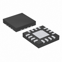
LTC3210EPD-1#TRPBF Linear Technology, LTC3210EPD-1#TRPBF Datasheet - Page 10

LTC3210EPD-1#TRPBF
Manufacturer Part Number
LTC3210EPD-1#TRPBF
Description
IC LED DRVR WHITE BCKLT 16-UTQFN
Manufacturer
Linear Technology
Type
Backlight, White LEDr
Datasheet
1.LTC3210EUD-1PBF.pdf
(16 pages)
Specifications of LTC3210EPD-1#TRPBF
Topology
Step-Up (Boost), Switched Capacitor (Charge Pump)
Number Of Outputs
5
Internal Driver
Yes
Type - Primary
Backlight
Type - Secondary
White LED
Frequency
800kHz
Voltage - Supply
2.9 V ~ 4.5 V
Mounting Type
Surface Mount
Package / Case
16-UTQFN (16-µTQFN)
Operating Temperature
-40°C ~ 85°C
Internal Switch(s)
Yes
Lead Free Status / RoHS Status
Lead free / RoHS Compliant
Voltage - Output
-
Current - Output / Channel
-
Efficiency
-
Available stocks
Company
Part Number
Manufacturer
Quantity
Price
operaTion
LTC3210-1
When the LTC3210-1 operates in either 1.5x mode or 2x
mode, the charge pump can be modeled as a Thevenin-
equivalent circuit to determine the amount of current
available from the effective input voltage and effective
open-loop output resistance, R
R
switching term, 1/(2f
tances and the nonoverlap period of the switching circuit.
However, for a given R
will be directly proportional to the advantage voltage of
1.5V
mode. Consider the example of driving white LEDs from
0
OL
is dependent on a number of factors including the
BAT
– CPO for 1.5x mode and 2V
Figure 3. Typical 1.5x R
Figure 2. Charge Pump Thevenin
Equivalent Open-Loop Circuit
3.8
3.6
3.4
3.2
3.0
2.8
2.6
2.4
–40
V
V
C2 = C3 = C4 = 2.2µF
BAT
CPO
= 3V
+
–
= 4.2V
–15
OSC
1.5V
OL
TEMPERATURE (˚C)
, the amount of current available
BAT
• C
R
OL
10
OR 2V
FLY
OL
OL
BAT
), internal switch resis-
35
vs Temperature
(Figure 2).
32101 F02
CPO
+
–
60
BAT
– CPO for 2x
32101 F03
85
a 3.1V supply. If the LED forward voltage is 3.8V and the
current sources require 100mV, the advantage voltage for
1.5x mode is 3.1V • 1.5 – 3.8V – 0.1V or 750mV. Notice
that if the input voltage is raised to 3.2V, the advantage
voltage jumps to 900mV— a 20% improvement in avail-
able strength.
From Figure 2, for 1.5x mode the available current is
given by:
For 2x mode, the available current is given by:
Notice that the advantage voltage in this case is 3.1V • 2
– 3.8V – 0.1V = 2.3V. R
nificant overall increase in available current is achieved.
Typical values of R
shown in Figure 3 and Figure 4.
I
I
OUT
OUT
=
=
( .
(
1 5
2
Figure 4. Typical 2x R
4.6
V
4.4
4.2
4.0
3.8
3.6
3.4
3.2
BAT
–40
V
R
BAT
V
V
C2 = C3 = C4 = 2.2µF
R
BAT
CPO
OL
–
OL
= 3V
= 4.8V
V
–
–15
OL
CPO
V
as a function of temperature are
CPO
OL
TEMPERATURE (˚C)
)
is higher in 2x mode but a sig-
10
)
OL
35
vs Temperature
60
32101 F04
85
32101fd


