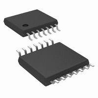
LM3406HVMHX/NOPB National Semiconductor, LM3406HVMHX/NOPB Datasheet - Page 8

LM3406HVMHX/NOPB
Manufacturer Part Number
LM3406HVMHX/NOPB
Description
IC LED DRVR HP CONS CURR 14TSSOP
Manufacturer
National Semiconductor
Series
PowerWise®r
Type
High Power, Constant Currentr
Datasheet
1.LM3406HVMHXNOPB.pdf
(32 pages)
Specifications of LM3406HVMHX/NOPB
Constant Current
Yes
Topology
PWM, Step-Down (Buck)
Number Of Outputs
1
Internal Driver
Yes
Type - Primary
Automotive
Type - Secondary
White LED
Frequency
1MHz
Voltage - Supply
6 V ~ 75 V
Mounting Type
Surface Mount
Package / Case
14-TSSOP Exposed Pad, 14-eTSSOP 14-HTSSOP
Operating Temperature
-40°C ~ 125°C
Current - Output / Channel
1.5A
Internal Switch(s)
Yes
Efficiency
96%
For Use With
876-1003 - LM3406 LED DRIVER EVAL BOARDLM3406MHEVAL - BOARD EVAL FOR LM3406MH
Lead Free Status / RoHS Status
Lead free / RoHS Compliant
Voltage - Output
-
Other names
LM3406HVMHX
Available stocks
Company
Part Number
Manufacturer
Quantity
Price
Part Number:
LM3406HVMHX/NOPB
Manufacturer:
TI/德州仪器
Quantity:
20 000
Block Diagram
Application Information
THEORY OF OPERATION
The LM3406 and LM3406HV are buck regulators with a wide
input voltage range, low voltage reference, and a fast output
enable/disable function. These features combine to make
them ideal for use as a constant current source for LEDs with
forward currents as high as 1.5A. The controlled on-time
(COT) architecture uses a comparator and a one-shot on-
timer that varies inversely with input and output voltage in-
stead of a fixed clock. The LM3406/06HV also employs an
integrator circuit that averages the output current. When the
converter runs in continuous conduction mode (CCM) the
controlled on-time maintains a constant switching frequency
over changes in both input and output voltage. These features
combine to give the LM3406/06HV an accurate output cur-
rent, fast transient response, and constant switching frequen-
cy over a wide range of conditions.
7
CONTROLLED ON-TIME OVERVIEW
Figure 1
used to control the current through an array of LEDs. A dif-
ferential voltage signal, V
flows through the current setting resistor, R
back by the CS pin, where it is integrated and compared
against an error amplifier-generated reference. The error am-
plifier is a transconductance (G
voltage on COMP to maintain a 200 mV average at the CS
pin. The on-comparator turns on the power MOSFET when
V
power MOSFET conducts for a controlled on-time, t
an external resistor, R
voltage, V
plified equation (for the most accurate version of this expres-
sion see the Appendix):
At the conclusion of t
must remain off for a minimum of 230 ns. Once this t
is complete the CS comparator compares the integrated
V
SNS
SNS
and reference again, waiting to begin the next cycle.
falls below the reference created by the G
shows a simplified version of the feedback system
O
. On-time can be estimated by the following sim-
ON
ON
, the input voltage, V
the power MOSFET turns off and
SNS
, is created as the LED current
m
) amplifier which adjusts the
IN
SNS
and the output
. V
www.national.com
m
30020303
SNS
amp. The
ON
, set by
OFF-MIN
is fed


