NCP5604BMTR2G ON Semiconductor, NCP5604BMTR2G Datasheet - Page 7
NCP5604BMTR2G
Manufacturer Part Number
NCP5604BMTR2G
Description
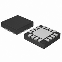
IC DRIVER LED WHITE HE 16-QFN
Manufacturer
ON Semiconductor
Type
Backlight, White LEDr
Datasheet
1.NCP5604AMTR2G.pdf
(15 pages)
Specifications of NCP5604BMTR2G
Topology
PWM, Switched Capacitor (Charge Pump)
Number Of Outputs
4
Internal Driver
Yes
Type - Primary
Backlight, Flash/Torch
Type - Secondary
White LED
Frequency
850kHz ~ 1.15MHz
Voltage - Supply
2.7 V ~ 5.5 V
Voltage - Output
4.8 V ~ 6 V
Mounting Type
Surface Mount
Package / Case
16-TFQFN Exposed Pad
Operating Temperature
-40°C ~ 85°C
Current - Output / Channel
100mA
Internal Switch(s)
Yes
Efficiency
85%
Number Of Segments
3
Operating Supply Voltage
2.7 V to 5.5 V
Maximum Supply Current
1 mA
Maximum Power Dissipation
320 mW
Maximum Operating Temperature
+ 85 C
Mounting Style
SMD/SMT
Minimum Operating Temperature
- 40 C
Lead Free Status / RoHS Status
Lead free / RoHS Compliant
Other names
NCP5604BMTR2G
NCP5604BMTR2GOSTR
NCP5604BMTR2GOSTR
Available stocks
Company
Part Number
Manufacturer
Quantity
Price

Part Number:
NCP5604BMTR2G
Manufacturer:
ON/安森美
Quantity:
20 000


8. The total output current is evenly distributed across the external LED.
9. LED4 is not connected in the NCP5604B version.
10. The NCP5604B controls 75 mA in total in the three current mirrors, the extra 25 mA available current from the DC-DC converter being available
POWER SUPPLY SECTION
temperature, operating conditions 2.85 V < Vbat < 5.5 V, unless otherwise noted.)
5, 6, 7, 8
5, 6, 7, 8
for external purpose.
Pin
12
12
12
12
1
1
1
-
-
-
-
Symbol
Tstart
E
T
Fpwr
V
Isch
I
I
I
V
T
I
stdb
MAT
TOL
I
SDH
PWR
out
bat
out
op
SD
Power Supply
Continuous DC Current in the Load (Note 8)
Continuous Output Short Circuit Current
Output Voltage Compliance (OVP)
DC-DC Start Time (Cout = 1.0 mF)
Standby Current, @ Iout = 0 mA, EN = GND
Operating Current, @Iout = 0 mA, EN = H
Output LED to LED Current Matching, @ Vbat = 3.6 V,
Output Current Tolerance (Note 9)
Charge Pump Operating Frequency
Thermal Shutdown Protection
Thermal Shutdown Protection Hysteresis
Efficiency (Note 9)
@ Vf = 3.2 V, 3.3 V < Vbat < 5.5 V (Total Iout = 4*LED)
- from Vout = 0 V to full load operation, @ Vbat = nominal
Vbat = 3.6 V
Vbat = 4.2 V
2.85 V < Vbat < 5.5 V
Vbat = 3.6 V
I
@ 3.2 V < Vbat < 4.2 V, I
-25°C < T
LED1 to LED4 = 5.0 mA, Vf = 2.95 V (Total = 20 mA), Vbat = 3.2 V
LED1 to LED4 = 25 mA, Vf = 3.3 V (Total = 100 mA), Vbat = 3.8 V
LED
= 20 mA, LED1 to LED4 are identical (Note 9)
(Typical values are referenced to T
A
< 85°C
LED
NCP5604A, NCP5604B
Rating
= 20 mA
http://onsemi.com
A
7
= +25°C, Min & Max values are referenced -40°C to +85°C ambient
-2.0
-5.0
0.85
Min
100
2.7
4.8
-
-
-
-
-
-
-
-
-
-
"0.2
"1.0
Typ
100
160
0.3
0.4
1.0
1.0
40
30
87
85
-
-
-
-
Max
+2.0
+5.0
1.15
150
5.5
6.0
3.0
5.0
1.5
-
-
-
-
-
-
-
MHz
Unit
mA
mA
mA
mA
°C
°C
ms
%
%
%
V
V
Related parts for NCP5604BMTR2G
Image
Part Number
Description
Manufacturer
Datasheet
Request
R

Part Number:
Description:
High Efficiency White LED Driver
Manufacturer:
ON Semiconductor
Datasheet:
Part Number:
Description:
Current Mode Charge Pump Led Driver
Manufacturer:
ON Semiconductor
Datasheet:
Part Number:
Description:
ON Semiconductor [VOLTAGE REGULATOR]
Manufacturer:
ON Semiconductor
Datasheet:
Part Number:
Description:
357-036-542-201 CARDEDGE 36POS DL .156 BLK LOPRO
Manufacturer:
ON Semiconductor
Datasheet:
Part Number:
Description:
357-036-542-201 CARDEDGE 36POS DL .156 BLK LOPRO
Manufacturer:
ON Semiconductor
Datasheet:
Part Number:
Description:
357-036-542-201 CARDEDGE 36POS DL .156 BLK LOPRO
Manufacturer:
ON Semiconductor
Datasheet:
Part Number:
Description:
357-036-542-201 CARDEDGE 36POS DL .156 BLK LOPRO
Manufacturer:
ON Semiconductor
Datasheet:
Part Number:
Description:
357-036-542-201 CARDEDGE 36POS DL .156 BLK LOPRO
Manufacturer:
ON Semiconductor
Datasheet:
Part Number:
Description:
357-036-542-201 CARDEDGE 36POS DL .156 BLK LOPRO
Manufacturer:
ON Semiconductor
Datasheet:
Part Number:
Description:
357-036-542-201 CARDEDGE 36POS DL .156 BLK LOPRO
Manufacturer:
ON Semiconductor
Datasheet:
Part Number:
Description:
357-036-542-201 CARDEDGE 36POS DL .156 BLK LOPRO
Manufacturer:
ON Semiconductor
Datasheet:
Part Number:
Description:
357-036-542-201 CARDEDGE 36POS DL .156 BLK LOPRO
Manufacturer:
ON Semiconductor
Datasheet:
Part Number:
Description:
357-036-542-201 CARDEDGE 36POS DL .156 BLK LOPRO
Manufacturer:
ON Semiconductor
Datasheet:
Part Number:
Description:
Manufacturer:
ON Semiconductor
Datasheet: