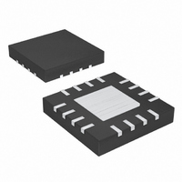
MAX16836ATE+ Maxim Integrated Products, MAX16836ATE+ Datasheet - Page 5

MAX16836ATE+
Manufacturer Part Number
MAX16836ATE+
Description
IC LED DRIVR HIGH BRIGHT 16-TQFN
Manufacturer
Maxim Integrated Products
Type
HBLED Driverr
Datasheet
1.MAX16836ATET.pdf
(11 pages)
Specifications of MAX16836ATE+
Topology
Linear (LDO), PWM
Number Of Outputs
1
Internal Driver
Yes
Type - Primary
Automotive
Type - Secondary
High Brightness LED (HBLED)
Voltage - Supply
6.5 V ~ 40 V
Voltage - Output
5V
Mounting Type
Surface Mount
Package / Case
16-TQFN Exposed Pad
Operating Temperature
-40°C ~ 125°C
Current - Output / Channel
350mA
Internal Switch(s)
Yes
Operating Supply Voltage
6.5 V to 40 V
Maximum Power Dissipation
2666.7 mW
Maximum Operating Temperature
+ 125 C
Mounting Style
SMD/SMT
Minimum Operating Temperature
- 40 C
Lead Free Status / RoHS Status
Lead free / RoHS Compliant
Frequency
-
Efficiency
-
Lead Free Status / Rohs Status
Details
(V
IN
4–8, 14
TQFN
1, 16
= V
2, 3
10
11
12
13
15
—
9
EN
PIN
Driver with PWM Dimming and 5V Regulator
= +12V, T
200Hz DIMMED OPERATION (EXPANDED)
High-Voltage, 350mA, High-Brightness LED
SO
—
—
8
1
2
3
4
5
6
7
_______________________________________________________________________________________
A
= +25°C, unless otherwise noted.)
20µs/div
NAME
GND
OUT
N.C.
CS+
DIM
CS-
EN
V5
EP
IN
I
V
DIM PULSED AT
200Hz (50%
DUTY CYCLE)
LOAD
IN
= V
= 350mA
EN
MAX16836 toc11
= 12V
Current-Regulated Output. Connect pin 1 to pin 16.
Positive Input Supply. Bypass IN with a 0.1µF (min) capacitor to GND. Connect pin 2 to pin
No Connection. Not internally connected.
Positive Input of the Internal Differential Amplifier. Connect the current-sense resistor
between CS+ and CS- to program the output current level.
Negative Input of the Internal Differential Amplifier. Connect the current-sense resistor
between CS- and CS+ to program the output current level.
+5V Regulated Output. Connect a 0.1µF capacitor from V5 to GND.
Ground
Pulsed Dimming Input. Drive DIM low to disable the output. Drive DIM high or leave
unconnected to enable the output.
Enable Input. Drive EN high to enable the output.
Exposed Pad. Connect to the ground plane for effective power dissipation. Do not use as
the only ground connection.
0V
V
2V/div
I
200mA/div
0A
LOAD
DIM
Typical Operating Characteristics (continued)
FUNCTION
206
204
202
200
198
0
0.5
1.0
1.5
V
SENSE
2.0
V
CS-
2.5
vs. V
(V)
Pin Description
3.0
CS-
I
3.5
LOAD
4.0
= 350mA
4.5
5.0
5


