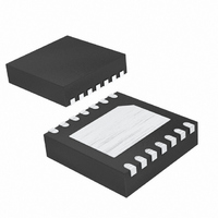
MAX8630WETD20+T Maxim Integrated Products, MAX8630WETD20+T Datasheet - Page 8

MAX8630WETD20+T
Manufacturer Part Number
MAX8630WETD20+T
Description
IC LED DRVR WHITE BCKLGT 14-TDFN
Manufacturer
Maxim Integrated Products
Type
Backlight, White LEDr
Datasheet
1.MAX8630XETD20T.pdf
(12 pages)
Specifications of MAX8630WETD20+T
Constant Current
Yes
Topology
PWM, Switched Capacitor (Charge Pump)
Number Of Outputs
5
Internal Driver
Yes
Type - Primary
Backlight
Type - Secondary
White LED
Frequency
1MHz
Voltage - Supply
2.7 V ~ 5.5 V
Voltage - Output
5V
Mounting Type
Surface Mount
Package / Case
14-TDFN Exposed Pad
Operating Temperature
-40°C ~ 85°C
Current - Output / Channel
25mA
Internal Switch(s)
Yes
Efficiency
93%
Lead Free Status / RoHS Status
Lead free / RoHS Compliant
125mA 1x/1.5x Charge Pumps for 5 White LEDs
in 3mm x 3mm TDFN
The MAX8630_ charge pump drives up to 5 white LEDs
(3 main LEDs and 2 sub LEDs) with regulated constant
current for uniform intensity. By utilizing adaptive 1x/1.5x
charge-pump modes and very low-dropout current regu-
lators, it achieves 125mA guaranteed output-drive capa-
bility and high efficiency over the 1-cell Li+ battery input
voltage range. 1MHz fixed-frequency switching allows
for tiny external components and the regulation scheme
is optimized to ensure low EMI and low input ripple. The
MAX8630X provides independent on/off/dimming control
for main and sub displays (see Figure 1). The
MAX8630W allows direct-PWM dimming of all five LEDs
together (see Figure 2). A functional diagram for the
MAX8630X/MAX8630W is shown in Figure 3.
When V
in 1x mode and V
current regulators regulate the LED current. As V
drops, V
threshold of 88mV, and the MAX8630_ starts switching
in 1.5x mode, and V
the charge pump. To switch back to 1x mode, the
MAX8630_ determines if V
V
makes this judgment is adaptive and matches the
switchover for the conditions.
The MAX8630_ includes soft-start circuitry to eliminate
inrush current at turn-on. When starting up, the output
capacitor is charged directly from the input with a
ramped current source (with no charge-pump action)
until the output voltage approaches the input voltage.
Once this occurs, the charge pump enters 1x mode,
Figure 4. MAX8630X EN_ Timing Diagram
8
LEDMIN
I
LED_
EN_
_______________________________________________________________________________________
SHUTDOWN
IN
LEDMIN_
greater than 88mV. The comparator that
is higher than V
0
INITIAL t
> 50μs
FULL
eventually falls below the switchover
OUT
t
SOFT-START
HI
LEDMIN
Detailed Description
is pulled up to V
OUT
IN
1x to 1.5x Switchover
1
- V
31/32
is regulated to 122mV by
, the MAX8630_ operates
OUT
2
30/32
is sufficient to keep
3
29/32
IN
. The internal
500ns TO 500μs
4
Soft-Start
28/32
5
27/32
t
LO
IN
6/32
and the LED output current is then ramped up in 32 lin-
ear steps. If the current regulators are in dropout at the
end of this time, the charge pump switches to 1.5x
mode. If the output is shorted to ground (V
1.25V), the part stays in the initial soft-start stage and
output current is limited by the ramped current source.
Additionally, when the main or sub LED current rolls
over from 1/32 to full, the LED current regulators soft-
start again to eliminate input current spikes.
When the LEDs are enabled (by driving EN_ high), the
MAX8630X goes through soft-start and brings the LED
current up in 32 linear steps. Dim the MAX8630X by puls-
ing EN_ low (500ns to 500µs pulse width). Each pulse
reduces the LED current by 1/32nd. After 31 pulses, the
current reaches 1/32, and the next pulse restores the cur-
rent to 100%. Figure 4 shows a timing diagram for EN_.
If dimming control is not required, ENM and ENS work
as simple on/off controls. Drive ENM/ENS high to
enable the LEDs, or drive ENM/ENS low for shutdown.
The LEDs operate at 100% brightness under these sim-
ple on/off conditions.
Dim the MAX8630W by applying a direct-PWM logic-
level signal to PWM. An internal resistor combined with
the capacitor at CPWM forms a lowpass filter that con-
verts the PWM signal to DC LED current that is propor-
tional to the PWM signal’s duty cycle. All five LEDS are
controlled together on the MAX8630W. The PWM fre-
quency range is 900Hz to 200kHz.
If dimming control is not required, PWM works as a sim-
ple on/off control. Drive PWM high to enable the LEDs,
or drive PWM low for shutdown.
>500ns
27
t
HI
5/32
ENM/ENS Dimming Control (MAX8630X)
28
4/32
PWM Dimming Control (MAX8630W)
29
3/32
30
2/32
31
1/32
32
FULL
31/32
t
SHDN
4ms
SHUTDOWN
OUT
<


