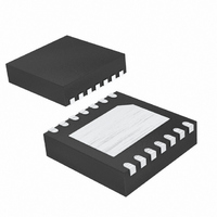
MAX8607ETD+T Maxim Integrated Products, MAX8607ETD+T Datasheet - Page 8

MAX8607ETD+T
Manufacturer Part Number
MAX8607ETD+T
Description
IC LED DRIVR PHOTO FLASH 14-TDFN
Manufacturer
Maxim Integrated Products
Type
Photo Flash LEDr
Datasheet
1.MAX8607ETDT.pdf
(10 pages)
Specifications of MAX8607ETD+T
Topology
Linear (LDO), PWM, Step-Up (Boost)
Number Of Outputs
1
Internal Driver
Yes
Type - Primary
Flash/Torch
Frequency
800kHz ~ 1.2MHz
Voltage - Supply
2.7 V ~ 5.5 V
Voltage - Output
5.5V
Mounting Type
Surface Mount
Package / Case
14-TDFN Exposed Pad
Operating Temperature
-40°C ~ 85°C
Current - Output / Channel
360mA, 1.5A
Internal Switch(s)
Yes
Efficiency
84%
Lead Free Status / RoHS Status
Lead free / RoHS Compliant
The MAX8607 is designed to use a 2.2µH inductor. To
prevent core saturation, ensure that the inductor-satura-
tion current rating exceeds the peak inductor current
for the application. Calculate the worst-case peak
inductor current with the following formula:
Table 2 provides a list of suggested inductors.
1MHz PWM Boost Converter for 1.5A
White LED Camera Flash
Figure 2. Typical Application Circuit
Table 2. Suggested Inductors
8
Coilcraft
Cooper (Coiltronics)
FDK
TOKO
2.7V TO 5.5V
10µF
C1
MANUFACTURER
INPUT
_______________________________________________________________________________________
SELECT
INPUTS
MODE-
I
PEAK
2.2µH
L1
=
0.1µF
5
C3
0 9
11, 12
V I
9, 10
.
×
3
1
2
×
LED MAX
LX
PGND
COMP
EN1
EN2
V
FLSH
IN MIN
5
(
(
R1
MAX8607
MIPW3226
FDSE0312
MIPF2520
DE2812C
LPO3310
SERIES
SD3114
U1
)
)
MOV
4
+
LGND
OUTS
Inductor Selection
GND
V
OUT
R2
LED
IN MIN
EP
(
2 2 2
13
14
7
6
8
×
)
.
×
INDUCTANCE
µ
0 5
H
.
(µH)
µ
2.2
2.2
2.2
2.2
2.2
2.2
s
C2
10µF
D1
Bypass the input to PGND using a ceramic capacitor.
Place the capacitor as close to the IC as possible. The
exact value of the input capacitor is not critical. The
typical value for the input capacitor is 10µF; however,
larger value capacitors can be used to reduce input
ripple at the expense of size and higher cost.
The output capacitance required depends on the
required LED current. A 10µF ceramic capacitor works
well in most situations, but a 4.7µF capacitor is accept-
able for load current below 300mA.
Due to fast switching waveforms and high-current paths,
careful PC board layout is required. Connect GND
directly to the exposed paddle underneath the IC; con-
nect the exposed paddle to the PC board ground plane.
Connect LGND and PGND to the ground plane. The out-
put bypass capacitor should be placed as close to the
IC as possible. C
COMP to GND as close to the IC as possible. Minimize
trace lengths between the IC and the inductor, the input
capacitor, and the output capacitor; keep these traces
short, direct, and wide. The ground connections of C
and C
connected to PGND. The traces from the input to the
inductor and from the output capacitor to the LED may
be longer. A sample layout is available in the MAX8607
evaluation kit (MAX8607EVKIT) to speed design.
PROCESS: BiCMOS
(mΩ)
DCR
150
100
160
83
80
70
OUT
should be as close together as possible and
I
1.48
SAT
(A)
1.1
0.7
1.1
1.6
2.3
COMP
(L
TYP
should be connected from
3.0 x 3.0 x 1.45 = 13mm
3.3 x 3.3 x 1.0 = 11mm
3.0 x 2.8 x 1.2 = 10mm
3.0 x 3.0 x 1.2 = 11mm
2.5 x 2.0 x 1.0 = 5mm
3.2 x 2.6 x 1.0 = 8mm
x W
Chip Information
Capacitor Selection
DIMENSIONS
TYP
PC Board Layout
x H
MAX
= Volume)
3
3
3
3
3
3
IN


