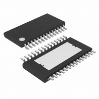
MAX16807AUI+T Maxim Integrated Products, MAX16807AUI+T Datasheet

MAX16807AUI+T
Specifications of MAX16807AUI+T
Related parts for MAX16807AUI+T
MAX16807AUI+T Summary of contents
Page 1
... TSSOP exposed paddle package. Pin Configuration appears at end of data sheet 5.5V R ________________________________________________________________ Maxim Integrated Products For pricing, delivery, and ordering information, please contact Maxim Direct at 1-888-629-4642, or visit Maxim’s website at www.maxim-ic.com. o Eight Constant-Current Output Channels (Up to 55mA Each) o ±3% Current Matching Among Outputs ...
Page 2
Integrated 8-Channel LED Driver with Switch-Mode Boost and SEPIC Controller ABSOLUTE MAXIMUM RATINGS V to AGND..........................................................-0.3V to +30V CC Current into V (V > 24V)...........................................±30mA PGND..............................................................-0.3V to +6V OUT to AGND.............................................-0. OUT Current (10µs ...
Page 3
Integrated 8-Channel LED Driver with Switch-Mode Boost and SEPIC Controller ELECTRICAL CHARACTERISTICS (PWM CONTROLLER) (continued +15V +3V to +5.5V referenced to PGND AGND 0V; all voltages are measured ...
Page 4
Integrated 8-Channel LED Driver with Switch-Mode Boost and SEPIC Controller ELECTRICAL CHARACTERISTICS (LED DRIVER) (V+ = +3V to +5.5V 0V; all voltages are measured with respect to PGND, unless otherwise noted. T AGND PGND to +125°C, ...
Page 5
Integrated 8-Channel LED Driver with Switch-Mode Boost and SEPIC Controller 5V TIMING CHARACTERISTICS (V+ = +4.5V to +5.5V 0V; all voltages are measured with respect to PGND, unless otherwise noted ...
Page 6
Integrated 8-Channel LED Driver with Switch-Mode Boost and SEPIC Controller 3.3V TIMING CHARACTERISTICS (V+ = +3V to < +4.5V AGND PGND to +125°C, unless otherwise noted. Typical values are +25°C.) (Notes 1, 5) ...
Page 7
Integrated 8-Channel LED Driver with Switch-Mode Boost and SEPIC Controller (V = +15V 5.5V 10kΩ Typical values are +25°C, unless otherwise noted.) A BOOTSTRAP UVLO vs. TEMPERATURE 10 ...
Page 8
Integrated 8-Channel LED Driver with Switch-Mode Boost and SEPIC Controller (V = +15V 5.5V 10kΩ Typical values are +25°C, unless otherwise noted.) A TIMING RESISTANCE vs. OSCILLATOR FREQUENCY ...
Page 9
Integrated 8-Channel LED Driver with Switch-Mode Boost and SEPIC Controller (V = +15V 5.5V 10kΩ Typical values are +25°C, unless otherwise noted.) A SUPPLY CURRENT vs. SUPPLY VOLTAGE ...
Page 10
Integrated 8-Channel LED Driver with Switch-Mode Boost and SEPIC Controller (V = +15V 5.5V 10kΩ Typical values are +25°C, unless otherwise noted.) A OUT_ CURRENT vs. OUT_ VOLTAGE ...
Page 11
Integrated 8-Channel LED Driver with Switch-Mode Boost and SEPIC Controller PIN NAME 1, 13, 28 N.C. No Connection. Not internally connected. Leave unconnected. 2 AGND Analog Ground 3 OUT MOSFET Driver Output OUT. Connects to the gate of the external ...
Page 12
Integrated 8-Channel LED Driver with Switch-Mode Boost and SEPIC Controller ode of a string of LEDs connected in series. The con- stant-current capability 55mA per output, set for all 8 outputs by an external resistor, R device ...
Page 13
Integrated 8-Channel LED Driver with Switch-Mode Boost and SEPIC Controller V+ 68W/L W/L 1.23 R 1.23V EST 995R SET Figure 1c. OUT_ Driver Internal Diagram Switch-Mode Controller Current-Mode Control Loop The advantages of current-mode control over voltage- mode control are ...
Page 14
Integrated 8-Channel LED Driver with Switch-Mode Boost and SEPIC Controller The oscillator frequency is then OSC + Reference Output REF reference output that can source 20mA. Bypass REF to ...
Page 15
Integrated 8-Channel LED Driver with Switch-Mode Boost and SEPIC Controller The MAX16807 also operates in a stand-alone mode (see the Typical Operating Circuits ). For use with a microcontroller, the MAX16807 features a 4-wire serial interface using DIN, CLK, LE, ...
Page 16
Integrated 8-Channel LED Driver with Switch-Mode Boost and SEPIC Controller LE CLK DIN DOUT OE OUT_ Figure 3. 4-Wire Serial-Interface Timing Diagram LE t LRF OUT_ LE t LRR OUT_ CLK t CRF OUT_ CLK t CRR OUT_ Figure 4. ...
Page 17
Integrated 8-Channel LED Driver with Switch-Mode Boost and SEPIC Controller Computing Power Dissipation Use the following equation to estimate the upper limit power dissipation (PD) for the MAX16807: ⎡ ∑ ⎢ PD DUTY ...
Page 18
Integrated 8-Channel LED Driver with Switch-Mode Boost and SEPIC Controller OUT CS AGND 5. BYP PGND SCLK CLK MOSI DIN µC MISO DOUT LOAD LE ENABLE OE SET R ...
Page 19
... Maxim cannot assume responsibility for use of any circuitry other than circuitry entirely embodied in a Maxim product. No circuit patent licenses are implied. Maxim reserves the right to change the circuitry and specifications without notice at any time. Maxim Integrated Products, 120 San Gabriel Drive, Sunnyvale, CA 94086 408-737-7600 ____________________ 19 © 2009 Maxim Integrated Products ...


