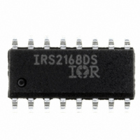
IRS2168DSTRPBF International Rectifier, IRS2168DSTRPBF Datasheet

IRS2168DSTRPBF
Specifications of IRS2168DSTRPBF
Available stocks
Related parts for IRS2168DSTRPBF
IRS2168DSTRPBF Summary of contents
Page 1
Features PFC, ballast control and 600 V half-bridge driver in one IC Critical-conduction mode boost-type PFC Programmable PFC over-current protection Programmable half-bridge over-current protection Programmable preheat frequency Programmable preheat time Programmable ignition ramp Programmable run frequency Closed-loop ignition current regulation ...
Page 2
Absolute Maximum Ratings Absolute maximum ratings indicate sustained limits beyond which damage to the device may occur. parameters are absolute voltages referenced to COM, all currents are defned positive into any lead. The thermal resistance and power dissipation ratings are ...
Page 3
Recommended Operating Conditions For proper operation the device should be used within the recommended conditions. Symbol V -V High-side floating supply voltage Steady state high-side floating supply offset voltage S V Supply voltage supply ...
Page 4
Electrical Characteristics (cont’ =14 V +/- 0. BIAS SD/EOL COMP CS OC Symbol PFC Error Amplifier Characteristics COMP pin OTA error amplifier output current ...
Page 5
Electrical Characteristics (cont’ =14 V +/- 0. BIAS SD/EOL COMP CS OC Symbol Ballast Control Oscillator Characteristics f Half-bridge oscillator run frequency OSC, RUN ...
Page 6
Electrical Characteristics (cont’ =14 V +/- 0. BIAS SD/EOL COMP CS Gate Driver Output Characteristics (HO, LO and PFC pins) V Low-level output voltage ...
Page 7
Schematic Block Diagram VCO 3 2V FMIN 4 2. FMIN R RFMIN VCC R CPH 1.2V 200ns Blank Time VBUS 1 4.0V COMP 6.5V Please Note: All values ...
Page 8
State Diagram SD/EOL > 5 (Lamp Removal < 10 (Power Turned Off) FAULT Mode Fault Latch Set 1 / -Bridge Off 2 ≅ 400 µA I QCCFLT CPH = ...
Page 9
Lead Assignments & Definitions VBUS 1 CPH 2 VCO 3 FMIN 4 COMP PFC www.irf.com HO Pin # Symbol 16 1 VBUS DC bus sensing input VS CPH Preheat timing input 2 15 ...
Page 10
Timing Diagrams Ballast Section VCC 15.6V UVLO+ UVLO- CPH (2/3)*VCC (1/3)*VCC 2V VCO FREQ HO 1.25V UVLO www.irf.com (RFMIN//RPH) PH IGN HO LO 1.25V CS IRS2168D(S)PbF RAMP PH VCO ...
Page 11
I. Ballast Section Functional Description Undervoltage Lockout Mode (UVLO) The undervoltage lockout mode (UVLO) is defined as the state the when V of the IC. To identify the different modes of the IC, refer to the State ...
Page 12
Preheat Mode (PH) The IRS2168D enters preheat mode when V the UVLO positive-going threshold (V MOSFET that connects pin CPH to COM is turned off and an external resistor (Fig. 3) begins to charge the external preheat timing capacitor (C ...
Page 13
Should this voltage exceed the internal threshold of 1 ignition regulation circuit controls the voltage on the VCO pin to increase the frequency slightly (see Fig. 6). This cycle-by-cycle feedback from ...
Page 14
Run Mode (RUN) Once V has exceeded 2/3*V CC second time, the IC enters run mode. CPH continues to charge The operating frequency is at the CC minimum frequency (after the ignition ramp) and is programmed ...
Page 15
II. PFC Section Functional Description In most electronic ballasts it is necessary to have the circuit act as a pure resistive load to the AC input line voltage. The degree to which the circuit matches a pure resistor is measured ...
Page 16
THD. Run Mode Signal VBUS 1 GAIN OTA1 4.0V 4.3V COMP 5 M1 COMP2 Discharge C1 M2 VCC to 3.0V UVLO- COMP3 ZX 6 2.0V 5.1V Figure 13: IRS2168D detailed PFC ...
Page 17
When this occurs discharged internally to UVLO. CC The IRS2168D enters UVLO mode and both the PFC and ballast sections are disabled. The start-up supply resistor together with the micro-power start-up current, CC should be ...
Page 18
IV. PFC Design Equations Step1: Calculate PFC inductor value: − PFC where, = VBUS = VAC RMS η OUT Step 2: Calculate peak PFC inductor current: ⋅ ⋅ ...
Page 19
IRS2168D(S)PbF Page 19 ...
Page 20
F www.irf.com LOADED TAPE FEED DIRECTION B NOTE : CONTROLLING E DIM ENSION CARRIER TAPE DIMENSION FOR 16SOICN Metric Code Min Max A 7.90 8.10 B 3.90 4.10 C 15.70 16.30 D 7.40 7.60 E 6.40 6.60 ...
Page 21
... SOIC Tape & Reel IRS2168DSTRPbF www.irf.com ORDER INFORMATION 16-Lead PDIP IRS2168DPbF 16-Lead SOIC IRS2168DSPbF This product has been designed and qualified for the industrial level. Qualification standards can be found at IR WORLD HEADQUARTERS: 233 Kansas St., El Segundo, California 90245, Tel: (310) 252-7105 Data and specifications subject to change without notice ...


