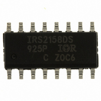
IRS2158DSPBF International Rectifier, IRS2158DSPBF Datasheet - Page 18

IRS2158DSPBF
Manufacturer Part Number
IRS2158DSPBF
Description
IC DVR HALF BRIDGE 600V 16-SOIC
Manufacturer
International Rectifier
Type
Fluorescent Lamp Driverr
Datasheet
1.IRS2158DPBF.pdf
(30 pages)
Specifications of IRS2158DSPBF
Frequency
42.5 ~ 48.5 kHz
Current - Supply
3.5mA
Current - Output
260mA
Voltage - Supply
11.5 V ~ 15.6 V
Operating Temperature
-40°C ~ 125°C
Package / Case
16-SOIC (3.9mm Width)
For Use With
IRPLDIM3 - KIT DES FLUOR BALLAST IRS2158D
Lead Free Status / RoHS Status
Lead free / RoHS Compliant
www.irf.com
Application Information and Additional Details
Information regarding the following topics is included as subsections within this section of the datasheet:
Under-voltage Lock-Out Mode (UVLO) Mode and IC Supply Circuitry
The under-voltage lock-out mode (UVLO) is defined as the state the IC is in when VCC is below the turn-on
threshold of the IC. To identify the different modes of the IC, refer to the State Diagram shown on page 14 of
this document. The IRS2158D undervoltage lock-out is designed to maintain an ultra low supply current of
less than 500 μA, and to guarantee the IC is fully functional before the high- and low-side output drivers are
activated.
IRS2158D together with a snubber charge pump from the half-bridge output (R
and D
The VCC capacitors (C
start-up current drawn by the IC. This resistor is chosen to set the desired AC line input voltage turn-on
threshold for the ballast. When the voltage at VCC exceeds the IC start-up threshold (VCCUV+) and the
VDC pin is above 5 V and the SD pin is below 3 V, the IC turns on and LO begins to oscillate. The
capacitors at VCC begin to discharge due to the increase in IC operating current (Figure 2). The high-side
supply voltage, VB-VS, begins to increase as capacitor C
MOSFET during the LO on-time of each LO switching cycle. When the VB-VS voltage exceeds the high-side
start-up threshold (VBSUV+), HO then begins to oscillate. This may take several cycles of LO to charge VB-
VS above VBSUV+ due to RDSon of the internal bootstrap MOSFET.
•
•
•
•
•
•
•
•
•
•
•
CP2
Under-Voltage Lock-Out (UVLO) Mode and IC Supply Circuitry
Preheat Mode (PH)
Ignition Mode (IGN)
Pre-Run Mode
Run Mode (RUN)
Dimming
SD/EOL and CS Fault Mode
Brown-out protection
Component Selection
Vcc double filter
PCB Layout Guidelines
).
Figure 1 shows an efficient supply voltage using the micro-power start-up current of the
VCC1
and C
Figure 1: Start-up and supply circuitry.
V
VCC2
V
RECT
V
BUS
BUS
(+)
(+)
(-)
) are charged by the current through supply resistor (R
IC
COM
IRS2158D
CONTROL
BSFET
BSFET
16
15
14
13
12
11
10
18
HO
VS
LO
CS
VB
VCC
COM
C
CS
R
R
R
C
R
C
3
HO
LO
BS
R
VCC
VCC1
2
C
VCC2
MHS
MLS
R
R
BS
CS
1
D
CP2
is charged through the internal bootstrap
C
D
CP1
SNUB
To Load
Return
Load
VCC
, C
© 2009 International Rectifier
VCC1
IRS2158D(S)
, C
VCC2
VCC
, C
) minus the
SNUB
, D
CP1


