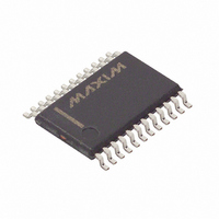
DS3881E+T&R/C Maxim Integrated Products, DS3881E+T&R/C Datasheet - Page 9

DS3881E+T&R/C
Manufacturer Part Number
DS3881E+T&R/C
Description
IC AUTO CCFL CTRLR 1CH 24-TSSOP
Manufacturer
Maxim Integrated Products
Type
CCFL Controllerr
Datasheet
1.DS3881EC.pdf
(28 pages)
Specifications of DS3881E+T&R/C
Frequency
40 ~ 100 kHz
Current - Supply
12mA
Voltage - Supply
4.75 V ~ 5.25 V
Operating Temperature
-40°C ~ 105°C
Package / Case
24-TSSOP
Lead Free Status / RoHS Status
Lead free / RoHS Compliant
Current - Output
-
Lead Free Status / Rohs Status
Details
The DS3881 uses a push-pull drive scheme to convert
a DC voltage (8V to 16V) to the high-voltage (300V
to 1000V
the CCFL. The push-pull drive scheme uses a minimal
number of external components, which reduces assem-
bly cost and makes the printed circuit board design
easy to implement. The push-pull drive scheme also
provides an efficient DC-to-AC conversion and pro-
duces near-sinusoidal waveforms.
Each DS3881 drives two logic-level n-channel
MOSFETs that are connected between the ends of a
step-up transformer and ground (see the Typical
Operating Circuit ). The transformer has a center tap on
the primary side that is connected to a DC voltage sup-
ply. The DS3881 alternately turns on the two MOSFETs
to create the high-voltage AC waveform on the sec-
ondary side. By varying the duration of the MOSFET
turn-on times, the CCFL current is able to be accurately
controlled.
A resistor in series with the CCFL’s ground connection
enables current monitoring. The voltage across this
resistor is fed to the lamp current monitor (LCM) input
and compared to an internal reference voltage to deter-
Figure 2. Per Channel Logic Diagram
512 x LAMP FREQUENCY
[20.48MHz ~ 51.20MHz]
DIMMING PWM SIGNAL
LAMP FREQUENCY
CHANNEL ENABLE
CHANNEL FAULT
[40kHz ~ 80kHz]
RMS
Single-Channel Automotive CCFL Controller
) AC waveform that is required to power
Detailed Description
CONTROLLER
DIGITAL
CCFL
_____________________________________________________________________
64 LAMP CYCLE
INTEGRATOR
RMS
LAMP MAXIMUM VOLTAGE REGULATION
LAMP STRIKE AND REGULATION
mine the duty cycle for the MOSFET gates. The CCFL
receives current monitoring and control, which maxi-
mizes the lamp’s brightness and lifetime.
Block diagrams of the DS3881 are shown in Figures 1
and 2. More operating details of the DS3881 are dis-
cussed on the following pages of this data sheet.
The DS3881 uses an I
communication with the on-board EEPROM and SRAM
configuration/status registers as well as user memory.
The configuration registers, which are a mixture of
shadowed EEPROM and SRAM, allow the user to cus-
tomize many DS3881 parameters such as the soft-start
ramp rate, the lamp and dimming frequency sources,
brightness of the lamps, fault-monitoring options, chan-
nel enabling/disabling, EMI control, and lamp current
overdrive control. The eight bytes of NV user memory
can be used to store manufacturing data such as date
codes, serial numbers, or product identification num-
bers. The device is shipped from the factory with the
configuration registers programmed to a set of default
configuration parameters. To inquire about custom pro-
gramming, contact the factory.
LOCE BIT IN CR1.0
Functional Diagrams (continued)
OVERVOLTAGE
LAMP OVERCURRENT
I 2 C-Compatible Serial Interface
LAMP OUT
Memory Registers and
2
C-compatible serial interface for
1.0V
300mV
2.5V
V
LRT
DRIVERS
GATE
(1.0V NOMINAL)
OVD1
OVERVOLTAGE DETECTOR
LCM1
LAMP CURRENT
MONITOR
GA1
GB1
DRIVERS
MOSFET
GATE
9


