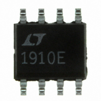
LT1910ES8#PBF Linear Technology, LT1910ES8#PBF Datasheet - Page 3

LT1910ES8#PBF
Manufacturer Part Number
LT1910ES8#PBF
Description
IC MOSFET DRIVER HIGH-SIDE 8SOIC
Manufacturer
Linear Technology
Datasheet
1.LT1910ES8PBF.pdf
(12 pages)
Specifications of LT1910ES8#PBF
Configuration
High-Side
Input Type
Non-Inverting
Delay Time
220µs
Number Of Configurations
1
Number Of Outputs
1
Voltage - Supply
8 V ~ 48 V
Operating Temperature
-40°C ~ 85°C
Mounting Type
Surface Mount
Package / Case
8-SOIC (3.9mm Width)
Lead Free Status / RoHS Status
Lead free / RoHS Compliant
Current - Peak
-
High Side Voltage - Max (bootstrap)
-
Available stocks
Company
Part Number
Manufacturer
Quantity
Price
ELECTRICAL CHARACTERISTICS
temperature range, otherwise specifi cations are at T
SYMBOL
I
V
V
V
t
t
t
Note 1: Stresses beyond those listed under Absolute Maximum Ratings
may cause permanent damage to the device. Exposure to any Absolute
Maximum Rating condition for extended periods may affect device
reliability and lifetime.
Note 2: The LT1910E is guaranteed to meet performance specifi cations
from 0°C to 70°C. Specifi cations over the –40°C to 85°C operating
temperature range are assured by design, characterization and correlation
TYPICAL PERFORMANCE CHARACTERISTICS
SENSE
ON
OFF
OFF(CL)
GATE
F(TH)
FOL
1.6
1.4
3.6
3.4
3.2
3.0
2.8
2.6
2.4
2.2
2.0
1.8
1.2
– V
0
Supply Current vs Supply Voltage
+
T
A
= 25°C
PARAMETER
Drain Sense Input Current
Gate Voltage Above Supply
FAULT Output High Threshold Voltage
FAULT Output Low Threshold Voltage
FAULT Output Low Voltage
Turn-On Time
Turn-Off Time
Current Limit Turn-Off Time
10
SUPPLY VOLTAGE (V)
20
OFF STATE
ON STATE
30
40
1910 G01
50
5.0
4.5
4.0
3.5
3.0
2.5
2.0
1.5
1.0
0.5
0
CONDITIONS
V
V
V
V
V
V
I
V
V
V
A
–50
F
+
+
+
+
+
IN
+
+
+
Supply Current vs Temperature
E-Grade
I-Grade
E-Grade
I-Grade
= 1mA
= 25°C. V
V
= 48V, V
= 8V
= 12V
= 24V
= 48V
= 24V, V
= 24V, V
= 24V, (V
+
= 2V, I
= 48V
–25
The
F
SENSE
GATE
GATE
= 1mA, Adjust V
+
0
l
TEMPERATURE (°C)
+
– V
= 12V to 48V unless otherwise noted.
denotes the specifi cations which apply over the full operating
= 32V, C
= 2V, C
SENSE
OFF STATE
= 65mV
ON STATE
25
with statistical process controls. The LT1910I is guaranteed to meet
performance specifi cations over the full –40°C to 125°C operating
temperature range.
Note 3: Guaranteed but not tested.
)→0.1V, C
GATE
50
GATE
T
= 1nF
= 1nF
75
GATE
100
1910 G02
= 1nF
125
l
l
l
l
l
l
2.0
1.8
1.6
1.4
1.2
1.0
0.8
–50
Input Voltage vs Temperature
MIN
100
3.1
3.0
10
10
10
10
4
7
–25
0
TEMPERATURE (°C)
0.07
TYP
220
0.5
4.5
8.5
3.4
3.3
12
12
12
12
25
20
25
50
MAX
LT1910
400
100
V
1.5
3.7
3.6
0.4
V
10
14
15
14
15
50
6
INH
INL
75
100
UNITS
1910 G03
1910fa
3
125
μA
μs
μs
μs
V
V
V
V
V
V
V
V
V


