TC4421AVAT Microchip Technology, TC4421AVAT Datasheet - Page 3
TC4421AVAT
Manufacturer Part Number
TC4421AVAT
Description
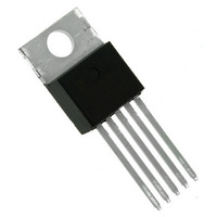
IC MOSFET DRIVER 9A INV TO220-5
Manufacturer
Microchip Technology
Type
Low Sider
Specifications of TC4421AVAT
Number Of Outputs
1
Configuration
Low-Side
Input Type
Inverting
Delay Time
38ns
Current - Peak
10A
Number Of Configurations
1
Voltage - Supply
4.5 V ~ 18 V
Operating Temperature
-40°C ~ 125°C
Mounting Type
Through Hole
Package / Case
TO-220-5 (Straight Leads)
Rise Time
34 ns
Fall Time
32 ns
Supply Voltage (min)
4.5 V
Supply Current
0.25 mA
Maximum Operating Temperature
+ 125 C
Mounting Style
Through Hole
Minimum Operating Temperature
- 40 C
Number Of Drivers
1
Lead Free Status / RoHS Status
Lead free / RoHS Compliant
High Side Voltage - Max (bootstrap)
-
Lead Free Status / Rohs Status
Lead free / RoHS Compliant
Available stocks
Company
Part Number
Manufacturer
Quantity
Price
Company:

Part Number:
TC4421AVAT
Manufacturer:
MICROCHIP
Quantity:
12 000


1.0
Absolute Maximum Ratings†
Supply Voltage ..................................................... +20V
Input Voltage .................... (V
Input Current (V
Package Power Dissipation (T
Package Power Dissipation (T
Thermal Impedances (To Case)
DC CHARACTERISTICS
2004 Microchip Technology Inc.
Electrical Specifications: Unless otherwise noted, T
Input
Logic ‘1’, High Input Voltage
Logic ‘0’, Low Input Voltage
Input Current
Output
High Output Voltage
Low Output Voltage
Output Resistance, High
Output Resistance, Low
Peak Output Current
Continuous Output Current
Latch-Up Protection
Withstand Reverse Current
Switching Time (Note 1)
Rise Time
Fall Time
Delay Time
Delay Time
Power Supply
Power Supply Current
Operating Input Voltage
Note 1:
5-Pin TO-220 .................................................... 1.6W
DFN .............................................................. Note 2
PDIP ............................................................ 730 mW
SOIC............................................................ 750 mW
5-Pin TO-220 (With Heatsink) ........................ 12.5W
5-Pin TO-220 R
2:
3:
ELECTRICAL
CHARACTERISTICS
Parameters
Switching times ensured by design.
Package power dissipation is dependent on the copper pad area on the PCB.
Tested during characterization, not production tested.
IN
> V
J-C
DD
...................................... 10°C/W
)................................... 50 mA
DD
A
A
+ 0.3V) to (GND – 5V)
70°C)
25°C)
Sym
V
R
I
V
V
R
V
I
V
I
REV
t
t
I
PK
DC
t
t
D1
D2
I
IN
OH
OH
DD
OL
OL
R
F
S
IH
IL
V
DD
Min
–10
2.4
4.5
– 0.025
—
—
—
—
—
—
—
—
—
—
—
—
2
A
= +25°C with 4.5V
>1.5
Typ
1.8
1.3
1.4
0.9
9.0
0.2
60
60
30
33
55
—
—
—
—
—
† Stresses above those listed under “Absolute Maximum
Ratings” may cause permanent damage to the device. These
are stress ratings only and functional operation of the device
at these or any other conditions above those indicated in the
operation sections of the specifications is not implied.
Exposure to Absolute Maximum Rating conditions for
extended periods may affect device reliability.
0.025
Max
+10
150
0.8
1.7
1.5
75
75
60
60
18
—
—
—
—
—
—
Units
mA
µA
µA
ns
ns
ns
ns
V
V
V
V
A
A
A
V
TC4421/TC4422
V
DD
0V V
DC TEST
DC TEST
I
I
V
10V
(TC4421/TC4422 CAT only) (Note 3)
Figure 4-1, C
Figure 4-1, C
Figure 4-1
Figure 4-1
V
V
Duty cycle
OUT
OUT
DD
IN
IN
18V.
= 3V
= 0V
= 18V
= 10 mA, V
= 10 mA, V
V
IN
DD
V
DD
Conditions
18V, T
2%, t
L
L
= 10,000 pF
= 10,000 pF
DD
DD
A
= 18V
= 18V
DS21420D-page 3
= +25°C
300 µsec
Related parts for TC4421AVAT
Image
Part Number
Description
Manufacturer
Datasheet
Request
R

Part Number:
Description:
9a High-speed Mosfet Drivers
Manufacturer:
Microchip Technology Inc.
Datasheet:
Part Number:
Description:
Manufacturer:
Microchip Technology Inc.
Datasheet:
Part Number:
Description:
Manufacturer:
Microchip Technology Inc.
Datasheet:
Part Number:
Description:
Manufacturer:
Microchip Technology Inc.
Datasheet:
Part Number:
Description:
Manufacturer:
Microchip Technology Inc.
Datasheet:
Part Number:
Description:
Manufacturer:
Microchip Technology Inc.
Datasheet:
Part Number:
Description:
Manufacturer:
Microchip Technology Inc.
Datasheet:
Part Number:
Description:
Manufacturer:
Microchip Technology Inc.
Datasheet:
Part Number:
Description:
Manufacturer:
Microchip Technology Inc.
Datasheet: