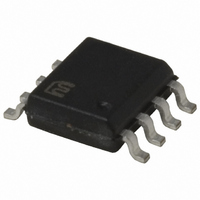
MIC4426BM Micrel Inc, MIC4426BM Datasheet - Page 7

MIC4426BM
Manufacturer Part Number
MIC4426BM
Description
IC DRIVER MOSFET 1.5A DUAL 8SOIC
Manufacturer
Micrel Inc
Datasheet
1.MIC4427ZM_TR.pdf
(9 pages)
Specifications of MIC4426BM
Rise Time
18ns
Mounting Type
Surface Mount
Configuration
Low-Side
Input Type
Inverting
Delay Time
17ns
Current - Peak
1.5A
Number Of Configurations
2
Number Of Outputs
2
Voltage - Supply
4.5 V ~ 18 V
Operating Temperature
-40°C ~ 85°C
Package / Case
8-SOIC (3.9mm Width)
Device Type
MOSFET
Driver Case Style
SOIC
No. Of Pins
8
Peak Output High Current, Ioh
1.5A
Supply Voltage Min
4.5V
Peak Reflow Compatible (260 C)
No
Number Of Drivers
2
Driver Configuration
Inverting
Driver Type
Low Side
Input Logic Level
CMOS/TTL
Fall Time
20ns
Propagation Delay Time
50ns
Operating Supply Voltage (max)
18V
Peak Output Current
1.5mA
Output Resistance
6Ohm
Operating Supply Voltage (min)
4.5V
Turn Off Delay Time
40fs
Turn On Delay Time (max)
60ps
Operating Temp Range
-40C to 85C
Operating Temperature Classification
Industrial
Mounting
Surface Mount
Pin Count
8
Package Type
SOIC
Lead Free Status / RoHS Status
Contains lead / RoHS non-compliant
High Side Voltage - Max (bootstrap)
-
Lead Free Status / RoHS Status
Not Compliant, Contains lead / RoHS non-compliant
Available stocks
Company
Part Number
Manufacturer
Quantity
Price
Company:
Part Number:
MIC4426BM
Manufacturer:
MICREL
Quantity:
28
Part Number:
MIC4426BM
Manufacturer:
MICREL/麦瑞
Quantity:
20 000
Applications Information
Supply Bypassing
Large currents are required to charge and discharge large
capacitive loads quickly. For example, changing a 1000pF
load by 16V in 25ns requires 0.8A from the supply input.
To guarantee low supply impedance over a wide frequency
range, parallel capacitors are recommended for power supply
bypassing. Low-inductance ceramic MLC capacitors with short
lead lengths (< 0.5”) should be used. A 1.0µF film capacitor
in parallel with one or two 0.1µF ceramic MLC capacitors
normally provides adequate bypassing.
Grounding
When using the inverting drivers in the MIC4426 or MIC4428,
individual ground returns for the input and output circuits or
a ground plane are recommended for optimum switching
speed. The voltage drop that occurs between the driver’s
ground and the input signal ground, during normal high-cur-
rent switching, will behave as negative feedback and degrade
switching speed.
Control Input
Unused driver inputs must be connected to logic high (which
can be V
(< 500µA) , connect unused inputs to ground. A logic-high
signal will cause the driver to draw up to 9mA.
The drivers are designed with 100mV of control input hys-
teresis. This provides clean transitions and minimizes output
stage current spikes when changing states. The control input
voltage threshold is approximately 1.5V. The control input
recognizes 1.5V up to V
1µA within this range.
The MIC4426/7/8 drives the TL494, SG1526/7, MIC38C42,
TSC170 and similar switch-mode power supply integrated
circuits.
April 2008
MIC4426/4427/4428
S
) or ground. For the lowest quiescent current
S
as a logic high and draws less than
7
Power Dissipation
Power dissipation should be calculated to make sure that the
driver is not operated beyond its thermal ratings. Quiescent
power dissipation is negligible. A practical value for total
power dissipation is the sum of the dissipation caused by the
load and the transition power dissipation (P
Load Dissipation
Power dissipation caused by continuous load current (when
driving a resistive load) through the driver’s output resistance
is:
For capacitive loads, the dissipation in the driver is:
Transition Dissipation
In applications switching at a high frequency, transition power
dissipation can be significant. This occurs during switching
transitions when the P-channel and N-channel output FETs
are both conducting for the brief moment when one is turning
on and the other is turning off.
Charge (Q) is read from the following graph:
P
P
P
L
L
T
= I
= f C
= 2 f V
Crossover Energy Loss per Transition
L
2
L
R
3×10
1×10
8×10
6×10
2×10
1×10
4×10
V
S
O
S
Q
-8
-9
-9
2
-9
-9
-9
-9
4
6
SUPPLY VOLTAGE (V)
8
10
12
14
16
L
+ P
18
M9999-042108
T
Micrel, Inc.
).


