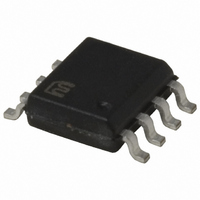
MIC5013BM Micrel Inc, MIC5013BM Datasheet - Page 12

MIC5013BM
Manufacturer Part Number
MIC5013BM
Description
IC DRIVER MOSF HI/LO SIDE 8SOIC
Manufacturer
Micrel Inc
Datasheet
1.MIC5013YM.pdf
(15 pages)
Specifications of MIC5013BM
Configuration
High or Low Side
Input Type
Non-Inverting
Delay Time
60µs
Number Of Configurations
1
Number Of Outputs
1
Voltage - Supply
7 V ~ 32 V
Operating Temperature
-40°C ~ 85°C
Mounting Type
Surface Mount
Package / Case
8-SOIC (3.9mm Width)
Number Of Drivers
1
Driver Type
High Side/Low Side
Operating Supply Voltage (max)
32V
Power Dissipation
1.25W
Operating Supply Voltage (min)
7V
Operating Supply Voltage (typ)
15V
Turn Off Delay Time
4us
Turn On Delay Time (max)
60us
Operating Temp Range
-40C to 85C
Operating Temperature Classification
Industrial
Mounting
Surface Mount
Pin Count
8
Package Type
SOIC
Lead Free Status / RoHS Status
Contains lead / RoHS non-compliant
Current - Peak
-
High Side Voltage - Max (bootstrap)
-
Lead Free Status / Rohs Status
Not Compliant
Available stocks
Company
Part Number
Manufacturer
Quantity
Price
Part Number:
MIC5013BM
Manufacturer:
MICREL
Quantity:
20 000
Company:
Part Number:
MIC5013BM/YM
Manufacturer:
MICREL
Quantity:
300
MIC5013
Applications Information
The top-side driver is based on the bootstrapped circuit of
Figure 6, and cannot be switched on indefinitely. The boot-
strap capacitor (1µF) relies on being pulled to ground by the
bottom-side output to recharge. This limits the maximum
duty cycle to slightly less than 100%.
Two of these circuits can be connected together to form
an H-bridge. If the H-bridge is used for locked antiphase
control, no special considerations are necessary. In the case
of sign/magnitude control, the “sign” leg of the H-bridge
should be held low (PWM input held low) while the other
leg is driven by the magnitude signal.
If current feedback is required for torque control, it is avail-
able in chopped form at the bottom-side driver's 22 mΩ
current-sensing resistor.
Time-Delay Relay (Figure 12). The MIC5013 forms the
basis of a simple time-delay relay. As shown, the delay
commences when power is applied, but the 100 kΩ/1N4148
could be independently driven from an external source such
MIC5013
INPUT
PWM
22kΩ
2N3904
1N4148
22kΩ
(Continued)
220pF
20kΩ
10kΩ
1nF
10kΩ
Figure 11. Half-Bridge
1
2
3
4
Thresh
Sense
Source
Input
MIC5013
1
2
3
4
Motor Driver
Thresh
Source
Input
Sense
MIC5013
Fault
Gate
Gnd
12
V+
as a switch or another high-side driver to give a delay rela-
tive to some other event in the system.
Hysteresis has been added to guarantee clean switching
at turn-on. Note that an over-current condition latches the
relay in a safe, OFF condition. Operation is restored by
either cycling power or by momentarily shorting pin 1 to
ground.
Motor Driver with Stall Shutdown (Figure 13). Tachometer
feedback can be used to shut down a motor driver circuit
when a stall condition occurs. The control switch is a 3-way
type; the “START” position is momentary and forces the
driver ON. When released, the switch returns to the “RUN”
position, and the tachometer’s output is used to hold the
MIC5013 input ON. If the motor slows down, the tach output
is reduced, and the MIC5013 switches OFF. Resistor “R”
sets the shutdown threshold. If the output current exceeds
30A, the MIC5013 shuts down and remains in that condition
until the momentary “RESET” button is pushed. Control is
then returned to the START/RUN/STOP switch.
Fault
Gate
8
7
6
5
Gnd
V+
100nF
8
7
6
5
15kΩ
15V
1N5817
100Ω
+
1µF
10µF
+
15V
1N4001 (2)
IRF541
22mΩ
CP S L - 3
IRF541
22mΩ
CP S L - 3
(Dale)
(Dale)
M
12V,
10A Stalled
July 2005
Micrel, Inc.


