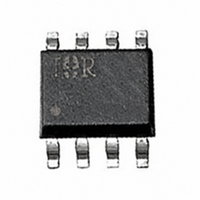
IR20153SPBF International Rectifier, IR20153SPBF Datasheet - Page 4

IR20153SPBF
Manufacturer Part Number
IR20153SPBF
Description
IC DRIVER HI SIDE RECHARGE 8-SOI
Manufacturer
International Rectifier
Datasheet
1.IR20153SPBF.pdf
(15 pages)
Specifications of IR20153SPBF
Configuration
High-Side
Input Type
Inverting
Delay Time
1.0µs
Current - Peak
400mA
Number Of Configurations
1
Number Of Outputs
1
High Side Voltage - Max (bootstrap)
150V
Voltage - Supply
5 V ~ 20 V
Operating Temperature
-55°C ~ 150°C
Mounting Type
Surface Mount
Package / Case
8-SOIC (3.9mm Width)
Lead Free Status / RoHS Status
Lead free / RoHS Compliant
IR20153S & (PbF)
Electrical Characteristics
Unless otherwise specified, V CC = 5V, V BS = 7V, V S = 0V, IN = 0V, RES = 5V, load R = 50 , C = 6.8nF (see Figure 3).
Unless otherwise noted, these specifications apply for an operating ambient temperature of T
Input Characteristics
Recharge Characteristics
Deadtime Characteristics
Gate Driver Characteristics cont.
V
Symbol
DT HOFF
V H_RES
V L_RES
t on_rech
t off_rech
DT HON
4
CC
V RECH
t res,on
R RES
V INH
V INL
R IN
Supply Characteristics
RES-to-Output Turn-On Propogation Delay
(50% input level to 10% [t plh ] output levels)
High Logic Level Input Threshold
Low Logic Level Input Threshold
High Logic Level Input Resistance
High Logic Level RES Input Threshold
Low Logic Level RES Input Threshold
High Logic Level RES Input Resistance
Recharge Transistor Turn-On Propogation Delay
Recharge Transistor Turn-Off Propogation Delay
Recharge Output Transistor On-State Voltage Drop
High Side Turn-Off to Recharge gate Turn-On
Recharge gate Turn-Off to High Side Turn-On0.
Definition
(see Figure 3a)
Min. Typ. Max. Units Test Conditions
0.4
40
40
3
3
7
7
-
-
-
-
-
100
100
1.0
0.3
0.8
11
11
-
-
-
-
-
220
220
2.0
1.4
1.4
0.9
1.2
1.5
15
15
-
-
A
k
k
sec
sec
sec
sec
sec
V
V
V
V
V
=25
°
C.
I S = 1mA, IN = 5V
V S = 5V
www.irf.com


